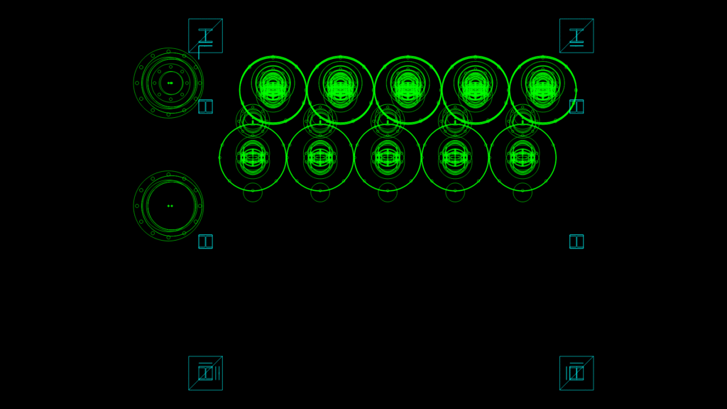
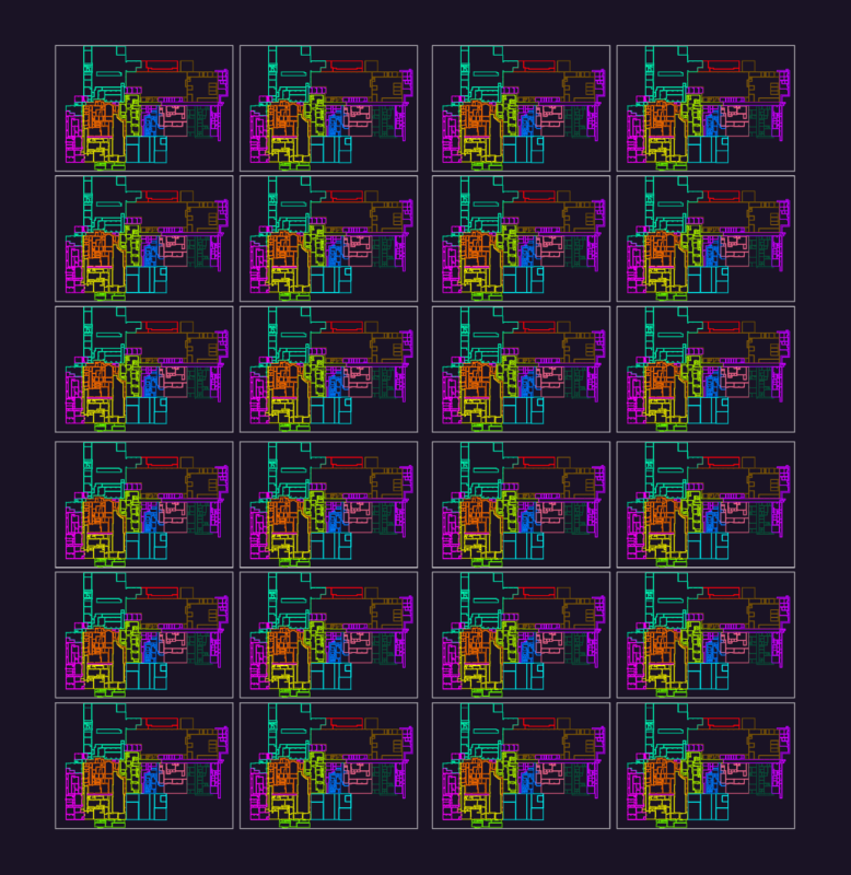
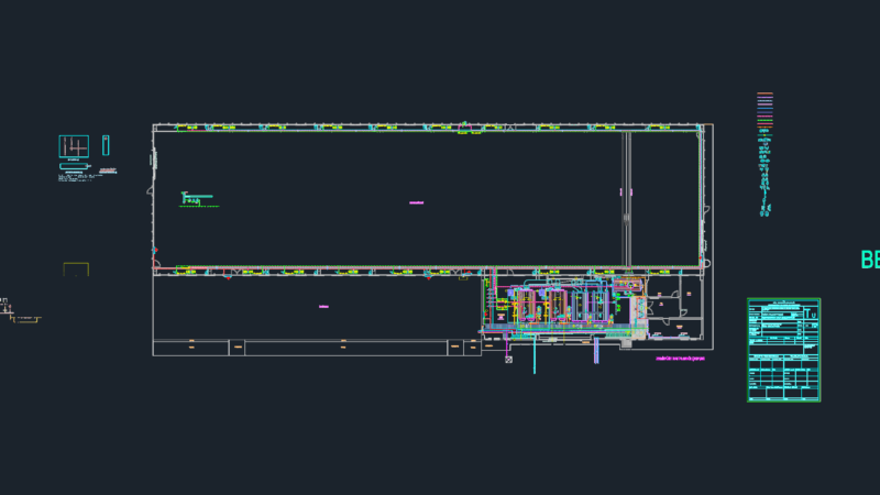
This technical drawing depicts a detailed arrangement of standardized pipe flanges with collars for an industrial piping system. The assembly features multiple circular components organized in a 2×5 grid configuration with two separate larger flanged connections on the left side. The drawing shows various flange sizes including FL125, FL150, and FL350 models with corresponding collar components (COLL125, COLL150, COLL350). Several concentric circles in each flange represent bolt hole patterns and gasket seating surfaces critical for proper sealing. The uniform spacing between components allows for efficient assembly while maintaining required clearances for maintenance access. Noteworthy is the implementation of standardized mounting patterns that ensure compatibility with common pipe dimensions in industrial applications. The drawing’s block references indicate this is likely part of a modular piping system designed for high-pressure fluid transport in process engineering applications.
Mechanical Flange and Collar assembly Detail for Industrial Piping