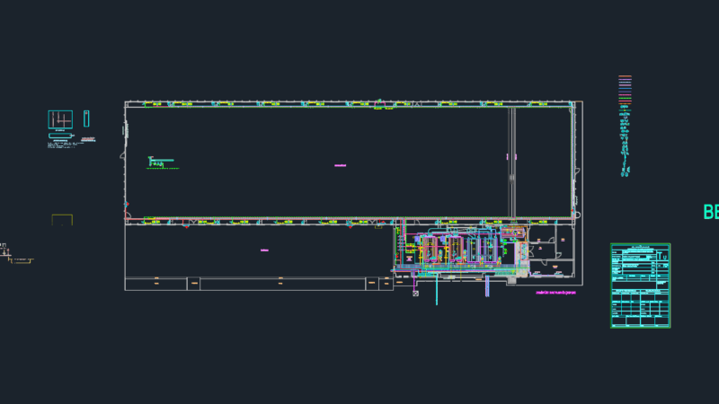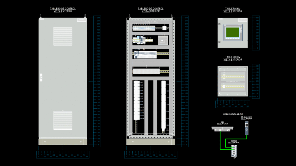
Comprehensive technical drawing showing multiple views of an industrial thermometry control system cabinet (TC). The drawing includes detailed front and interior elevations of the main control cabinet (2100mm x 800mm), and separate HMI (Human-Machine Interface) panel views with integrated display screen. The interior elevation reveals a well-organized component layout including:
– Terminal strips (XAI series) for analog inputs
– Digital I/O terminals (XDI/XDO series)
– Control components including circuit breakers/switches
– PLC or controller system with multiple modules
– Dedicated copper grounding bar (25x5mm)
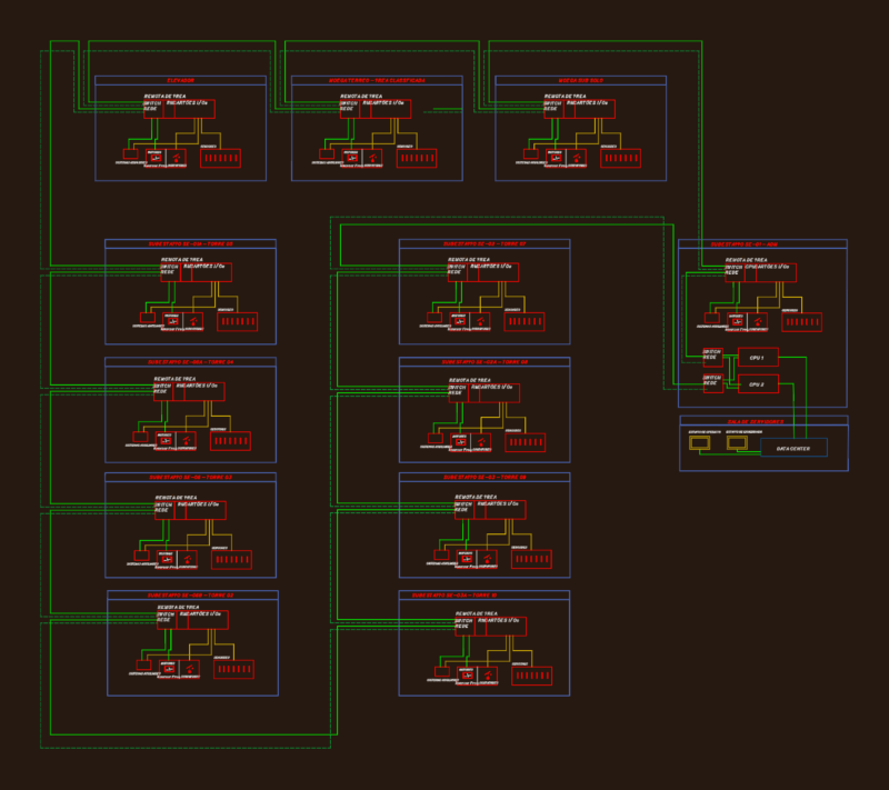
The network architecture diagram shows the communication between the HMI panel, switch, and control cabinet, indicating an integrated monitoring system. The cabinet appears to use standard DIN rail mounting for components with proper spacing for ventilation through louvered panels. All dimensions are provided in millimeters with a comprehensive coordinate system for precise component placement. This drawing represents the as-built documentation (rev C1) of the thermometry monitoring system.