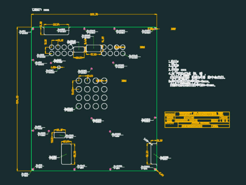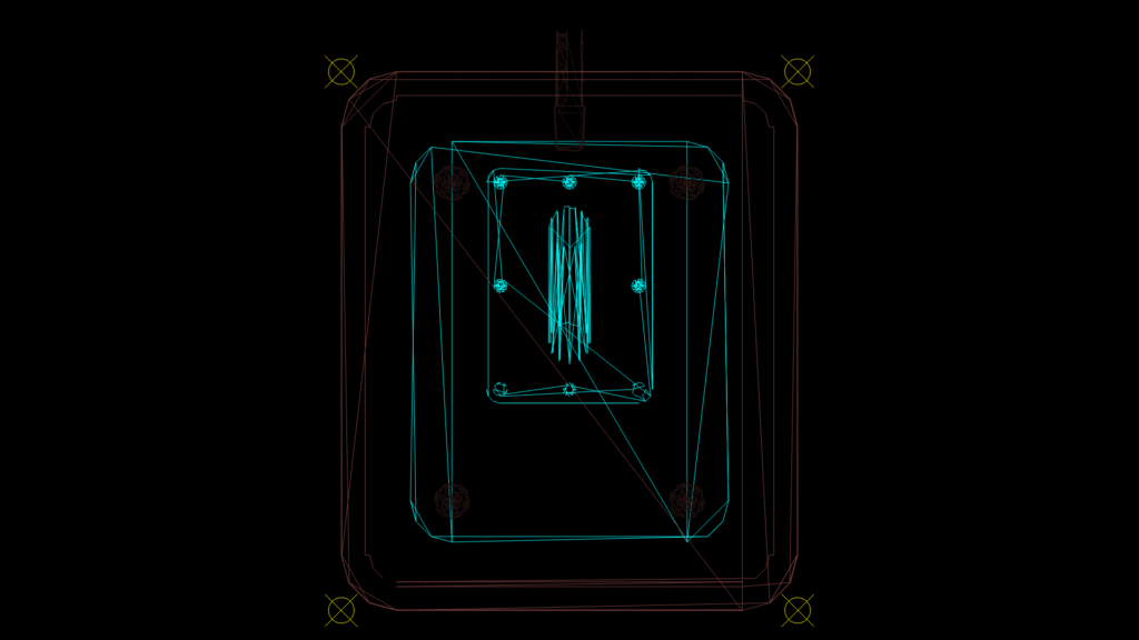
Military-grade utility terminal enclosure schematic with multiple layer configuration for specialized installations. The drawing features concentric housings with mounting points designated by crosshairs at each corner. The outer enclosure (red outline) provides structural protection while the inner housing (cyan) contains terminal connection points and central vertical component array. Key design elements include:
Design Features:
– Nested enclosure system with reinforced corners
– Four-point mounting configuration for secure installation
– Central vertical access shaft for cable management
– Multiple connection points positioned at strategic locations
– Layer separation for electromagnetic isolation and environmental protection
The AFUTL layer naming convention indicates Air Force Utility applications with dedicated layers for top plates (TPLM), base plates (BSPT), guide plates (GDPL), and support structures (SUPT). Terminal dimensions conform to military specification standards for field deployment scenarios.