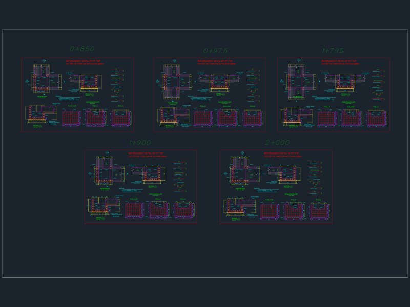
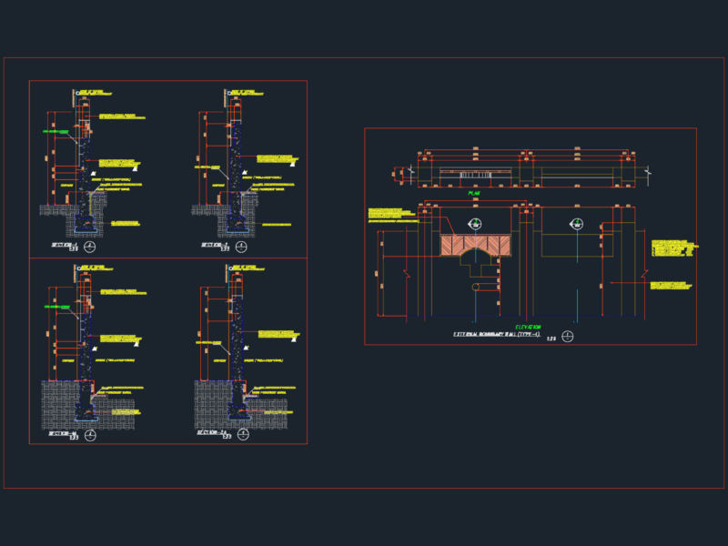
This drawing presents 16 comprehensive architectural expansion joint details for various building conditions. It features C/S Group expansion joint systems including GFT-100, GFT-200, GFW-200, GFS-200, GFP-200HD, FCF-200, FCF-500, FCFC-200, and FCFC-500 series. The details cover gaps ranging from 25mm to 100mm for floor-to-floor, floor-to-wall, wall-to-wall, and ceiling-to-ceiling/wall interfaces. Each detail includes specific fire barrier systems (RFX-1F, RFX-2F, MFX-2F/2W) with 2-hour UL ratings (FF-D-0044, WW-D-0050, WW-D-0052). The assemblies utilize extruded aluminum frames, santoprene gaskets, stainless steel spring clips, and specific mounting hardware with precise spacing requirements (typically 18″ O.C.). Notable components include continuous flexible gaskets, recessed aluminum center plates, and appropriate fire barriers. The 1:4 and 1:5 scale sections provide critical installation details for both interior applications and external elevations, with particular attention to waterproofing at roof conditions using SBS membranes and polystyrene insulation.
Architectural Expansion Joint Detail sections for Floor, Wall, and Ceiling