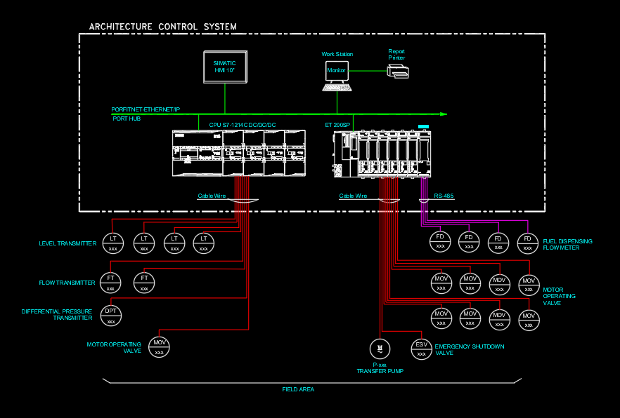
This Architecture Control System drawing presents a comprehensive industrial automation network designed for monitoring and controlling field equipment through a centralized PLC-based control system. The architecture illustrates communication between the Siemens SIMATIC HMI, Siemens S7-1200 PLC CPU, ET200SP Remote I/O, engineering workstation, report printer, and field instrumentation.
The system utilizes PROFINET/Ethernet IP communication for high-speed data exchange between the PLC, HMI, and Remote I/O, while RS-485 communication is used for fuel dispensing flow meters. The field devices include level transmitters (LT), flow transmitters (FT), differential pressure transmitters (DPT), motor-operated valves (MOV), transfer pumps, and emergency shutdown valves (ESV), providing complete process monitoring and control.
This drawing demonstrates signal flow from field instruments to the PLC controller, enabling real-time data acquisition, remote operation, process automation, alarm management, and equipment protection. It serves as an excellent reference for industrial automation projects, oil & gas facilities, water treatment plants, fuel distribution systems, manufacturing industries, and process control engineering.