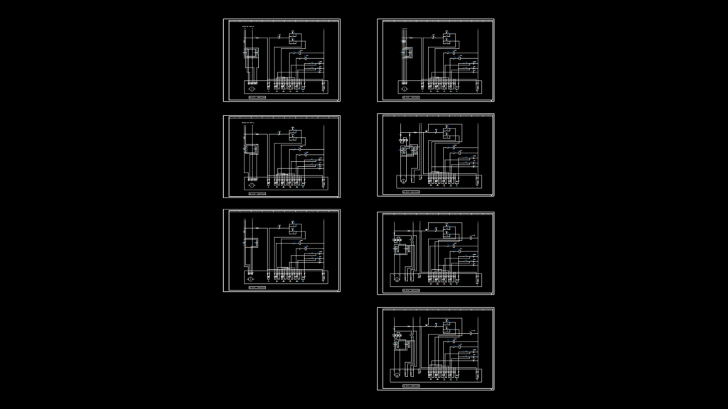
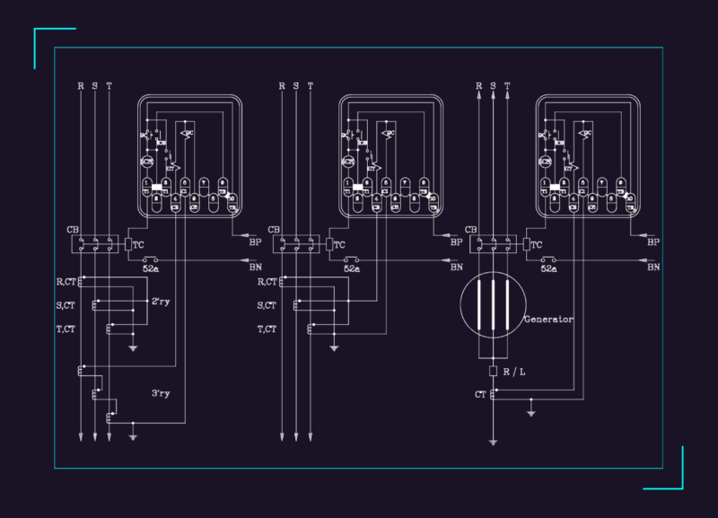
Comprehensive electrical wiring schematics for AUMA valve actuators depicting various control configurations across multiple voltage ratings (110-120VAC, 220-240VAC, and DC models). This diagrams illustrate terminal connections for standard ASV series actuators including models 141.1111, 151.1121, 111.1111, 185.1111, 195.1121, and 195.1111. Each schematic details proper wiring for control functions (OPEN, CLOSE, STOP), status indicators (OPEN, CLOSED, FAULT), limit switches (S1-S5), and thermal protection (TH). Terminal blocks clearly identify power supply connections (L1, N, PE for AC models; L+, L-, PE for DC variants) with appropriate voltage ratings. The drawings follow international electrical standards with dedicated sections for motor controls, position feedback, and thermal protection circuits—essential for proper installation in industrial valve automation systems.
AUMA Electric Actuator Wiring Diagrams for Multiple Supply Voltages