DETILS UNIONS METAL STRUCTURE
Drawing labels, details, and other text information extracted from the CAD file:
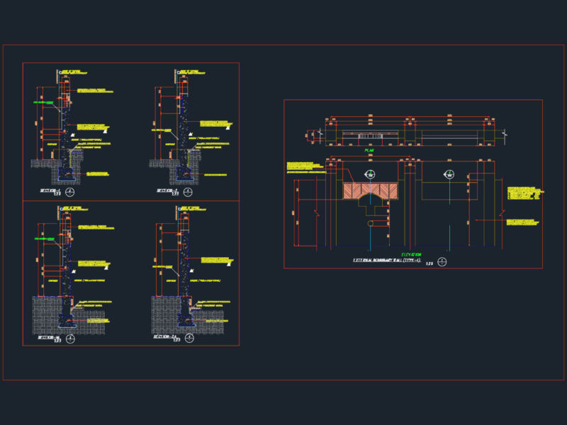
min. clearance, all around, provide clearance, between side plate, and beam, anchor bolts, side view, end view, figure, common beam seat., used to resist uplift and horizontal, forces as well as gravity loads. in, the case of the notched beam, effect must be checked. the beam, may be fastened to the tabs with, one or more bolts where forces, are with bolts and shear, plates., figure, similar to the detail in, figure except the side plates are, vertical which provides less end, distance for the bolts and may lessen, their resistance to horizontal forces., end view, side view, side plates welded, to bearing plate, fig. for, anchor bolts, side view, figure, shows steel angles, with separate bearing plate with, only the anchor bolts being cast in, place., clip angles, bearing plate, not welded, together, end view, anchor bolts, timber construction standards, min. clearance, all around, min. clearance, all around, bearing plate, shape corners, of beam to, clear weld to, obtain bearing, end view, side view, figure, this detail illustrates, typical taper end cut sometimes, referred to as fire cut. the end, of the beam is tapered so that the, top of the beam does not hit the, top of the wall recess if the beam, deflects excessively during fire., wall recess, figure, this detail may be, used when the pilaster is not wide, enough for outside anchor bolts., the may be welded to, the underside of the bearing plate, or the bolts and nuts may be, located in holes counterbored into, the bottom of the beam. this detail, is for use where the width of the, connection must be minimized or, appearance is important., maximum taper cut, to face of support, min. clearance, side view, end view, counterbore for bolt, extension and nut, anchor bolts along, beam centerline, side plates welded, to bearing, plate, typical construction aitc, min. clearance, all around beam, min. clearance, max., figure, simple beam anchorage., resists small uplift and horizontal, forces. bearing plate or moisture, barrier is recommended. provide, in. minimum clearance from all wall, contact sides and tops, masonry exists above beam, hole through beam, larger than bolt, bearing plate, anchor bolt, sloped seat welded, between vertical, parts of connection, figure, lateral support of the ends of beams, can be provided with clip angles anchored to the, wall but without connection to the beam. this, will not restrain vertical movement due to end, rotation or beam shrinkage. see detail, counterbore for, nut and washer if, flush surface req’d., figure, sloped beam upper end., the support at the top end of sloped, member should be designed with, sloping seat rather than notched end., the bolt must be designed to resist the, component of the, vertical beam reaction. see detail, beam not fastened, to clip angle, figure, sloped beam lower, end. the taper cut beam should be, in bearing contact with the bearing, plate. see detail, end restraint is, required to prevent, lateral rotation, timber construction standards, min. clearance, clearance, supported, member, figure, the vertical reaction of the, supported member is carried by the side plates, and transferred in bearing p