Pneumatic Cylinder Assembly Technical Overview
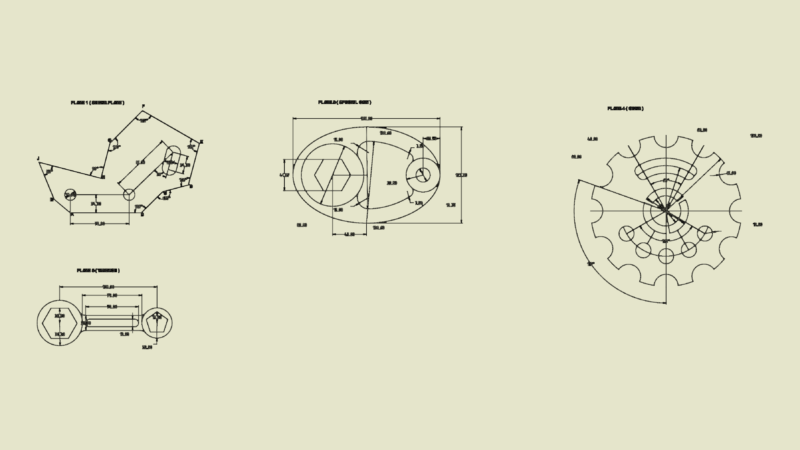
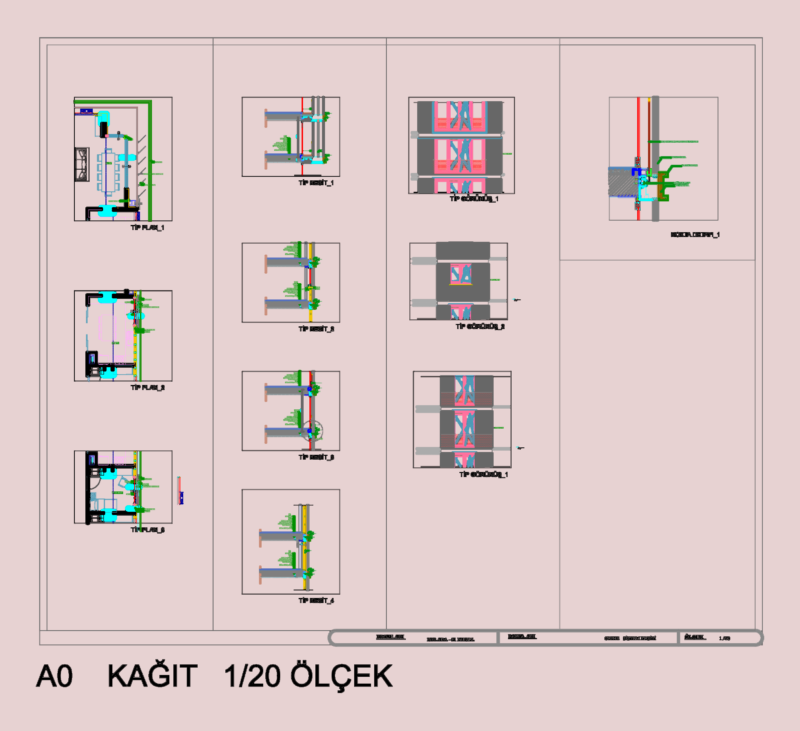
This sectional drawing depicts a detailed assembly of an inflatable hydraulic cylinder (Şişme Silindir) with an overall length of approximately 920mm. The cross-sectional view illustrates the internal components and mechanisms that enable the cylinder’s operation.
Key Components:
– Central steel cylinder body (‘Çelik Silindir’ layer) serving as the primary pressure vessel
– Piston assembly with sealing elements visible in the central section
– End caps/covers (‘Kapak-1A’ layer) with mounting provisions on both ends
– Shaft/rod (‘Mil’ layer) extending through the cylinder body
– Spacer bushings (‘Mesafe Burcu’ layer) for proper component alignment
– Mold components (‘Kalıp’ and ‘Üst Kalıp’ layers) likely for manufacturing or operation
The assembly utilizes multiple sealing interfaces to maintain pressure integrity during operation. The drawing shows careful attention to the connection methods between the cylinder body and end caps, which is critical for preventing leakage under pressure. The shaft appears to be precision-machined to accommodate proper sealing while allowing smooth linear motion.
This type of pneumatic/hydraulic assembly is commonly used in industrial applications where controlled linear force and motion are required, such as in manufacturing equipment, material forming processes, or specialized mechanical systems.