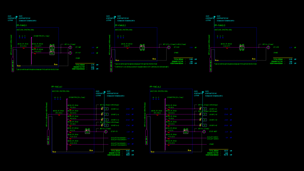
A comprehensive electrical single line diagram for a building’s HVAC (VAC) power distribution system. This drawing details five distribution panels: PP-FAN.D.1, PP-FAN.D.2, PP-FAN.D.3, PP-VAC.A.1, and PP-VAC.A.2, all operating at 400/230V, 3-phase/1-phase, 50Hz.
Panel Specifications:
– PP-VAC.A.1: 111.02 kW total load with 0.90 demand factor (99.91 kW actual load), fed from DB-A with 175-250A MCCB and copper bar TPN (20x5mm)
– PP-VAC.A.2: 123.11 kW total load with 0.90 demand factor (110.79 kW actual load), fed from DB-A with 175-250A MCCB
– PP-FAN.D.1: 2.75 kW total load with 0.90 demand factor (2.48 kW actual load), fed from MDB-ME.D with 17.5-25A MCCB
– PP-FAN.D.2: 5.50 kW total load with 1.00 demand factor, featuring EF.1-DG (5.50 kW) with Y/D starter
– PP-FAN.D.3: 2.20 kW total load with 1.00 demand factor, featuring EF.1-PR (2.20 kW) with DOL starter
Major Connected Equipment:
– VRF outdoor units (OU.VRF series) with loads ranging from 17.40-36.00 kW
– Exhaust fans (EF series) with motor loads ranging from 1.00-5.50 kW
– Elevator equipment with 1.91 kW loads
The diagram includes protection details with MCCB ratings, cable specifications (primarily NYY type), starter types (DOL/Y-D), and system interlocks. Notable is the EF.1-DG fan with interlock to operate only when the generator is off.