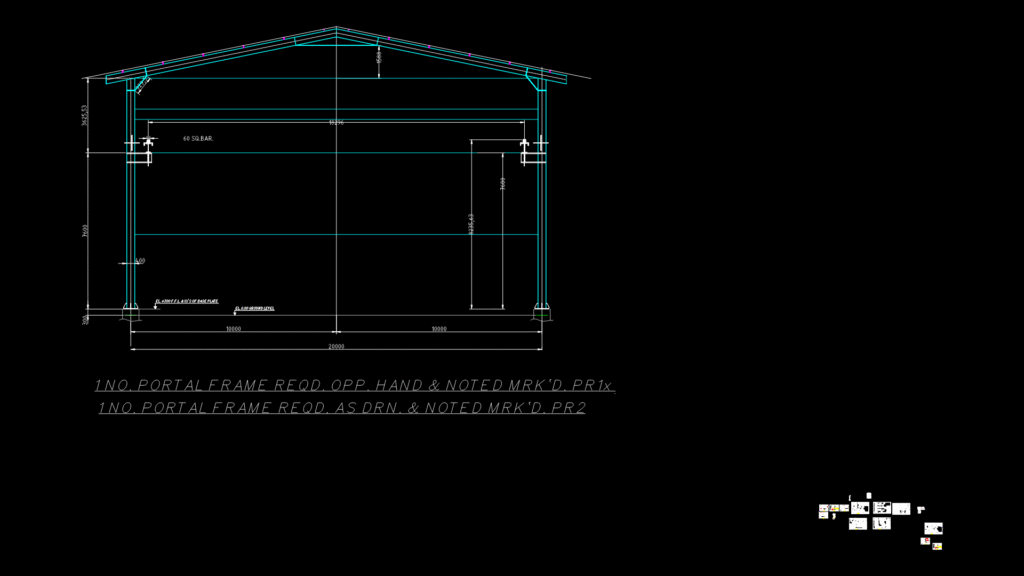
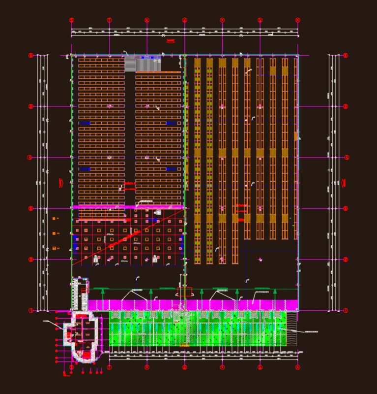
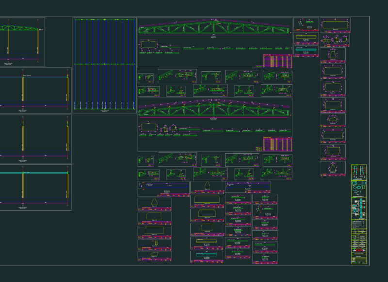
This structural drawing details the main portal frame configuration for an overhead crane extension at an engine workshop. The design features ISMB-350 steel sections for the primary frame with a 20-meter span (two 10-meter bays) and approximately 7-meter height. The portal frame includes gable columns with specific bracing requirements, with variations noted for three portal types (PR1, PR2, and PR3). Connection details show 25mm diameter high-strength bolts with 27mm holes at critical junctions, and multiple splice configurations. The structure uses IS:2062 Grade-A steel throughout with a total estimated weight of 4.748 tonnes per frame. The design incorporates eaves line detailing and provisions for crane rail mounting as per manufacturer specifications. All connections feature standardized 6mm fillet welds unless otherwise noted, with M16 bolts in 17.5mm holes used for general erection purposes. The foundation is shown with a 300mm elevation above the finished floor level.
Steel Portal Frame Section for Industrial Overhead Crane Extension