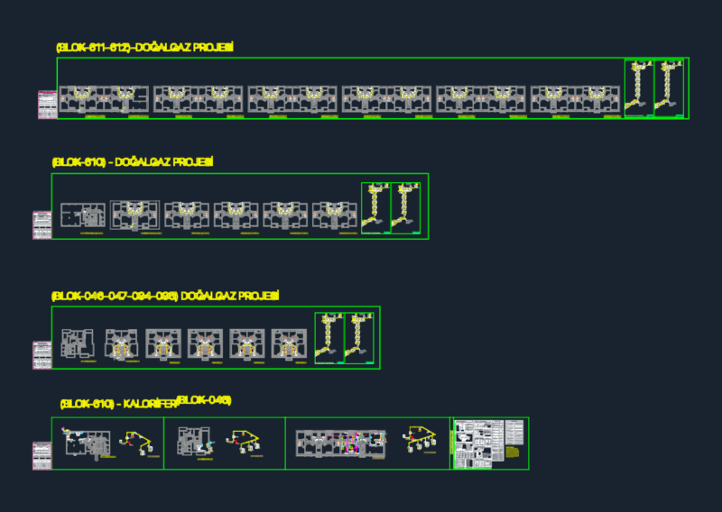
Comprehensive mechanical-electrical plan for a 529.2 m² cafeteria facility featuring VRF (Variable Refrigerant Flow) HVAC system integration with power distribution. This drawing includes:
HVAC Components:
– 13 ceiling-mounted 4-way cassette VRF indoor units (twelve 5.6 kW cooling/6.3 kW heating units and two 3.6 kW cooling/4.0 kW heating units)
– Outdoor VRF unit group with 78.6 kW cooling/88.2 kW heating capacity and 21 kW electrical consumption
– Kitchen exhaust system with 3000 m³/h airflow rate and 1.0 kW fan motors
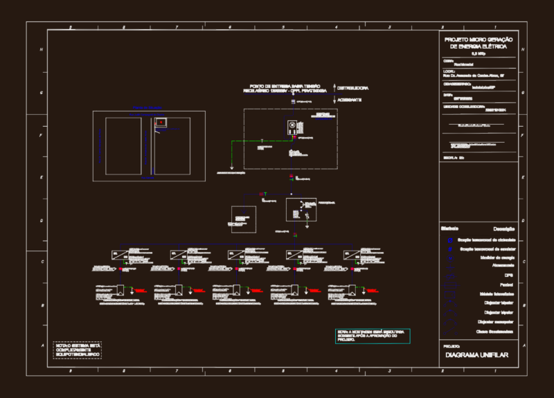
Electrical Distribution:
– Main distribution panel (ADP) with 49.81 kW connected load
– Ground floor distribution panel (ZK-DP) with 46.19 kW connected load
– Kitchen distribution panel (KD-DP) with 3.62 kW connected load
– Detailed circuit breaker configurations including TMŞ (thermomagnetic switches) and KAKR (residual current protection devices)
– Power cable specifications using N2XH, NHXMH FE180/PH90 fire-resistant cables
The drawing incorporates single-line diagrams, cable sizing tables, and detailed connection schematics with proper surge protection, equipotential bonding, and emergency shutdown systems compliant with local electrical standards.