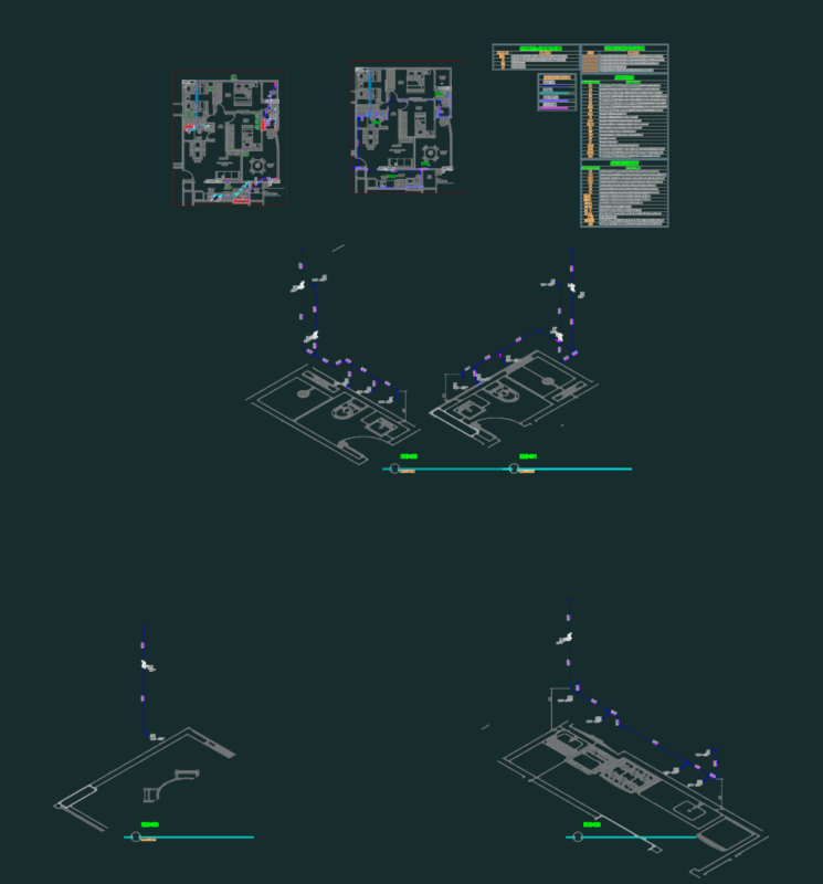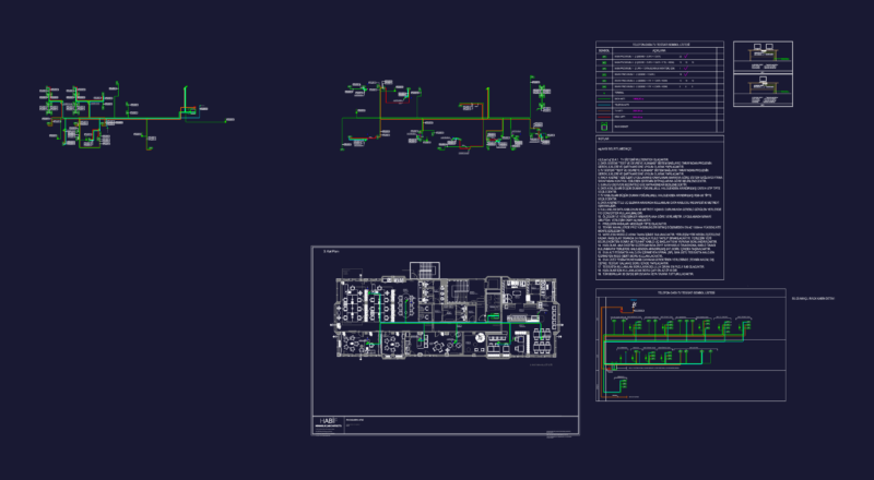
Electric Line Diagram in low voltage
Drawing labels, details, and other text information extracted from the CAD file (Translated from Spanish):
internal revision, r.m., for customer feedback, r.m., customer agreement, r.m., defi nitive lift of the turret station no., archive:, date:, mca, date, by, vo.bo., num., plotting:, transformer, insulation, charger, rectifier, batteries, Bank of, static, switch, transfer, secondary supply, main supply, synchrony, investor, manual of, switch, manual switch, external maintenance, note, see plan, load center, kva, transformer, insulation, charger, rectifier, batteries, Bank of, static, switch, transfer, secondary supply, synchrony, investor, manual of, switch, manual switch, external maintenance, note, load center, kva, kva, transformer, insulation, charger, rectifier, batteries, Bank of, static, switch, transfer, secondary supply, synchrony, investor, manual of, switch, manual switch, external maintenance, note, load center, symbology, comes from, see plan, comes from, see plan, comes from, thermomagnetic switch, removable, frame amps, amperes of firing, notes, nomenclature, ccm, engine control Center, ups, uninterruptible power unit, sdc, digital monitoring system control, sgf, fire gas system, sis, safety instrumented system, vain, AC voltage, phase, threads, hertz, tab., board, this plan is complemented by the plans indicated in the table below., reference drawings., the protection data shown here are values, for this the values according to the information must be confirmed, definite of the selected equipment according to the adjustments, required., the force systems are covered in the specification, sfi, uninterruptible power system, main supply, main supply, see plan, comes from tab., see plan, comes from tab., see plan, comes from tab., power board, force circuit, wiring interconnection by manufacturer of ups., the main switch of the board is ordered from poles since, commercially there are no single poles to be used., itm, connection diagram, itm, load box, do not., cto., service, Watts, cto., do not., cto., do not., itm, connection diagram, itm, load box, do not., cto., service, Watts, cto., do not., cto., do not., switches: from, cabinet: type nema main switch poles., load connected:, load in operation:, total, distribution board fire gas system, comes from, reservation, kva, kva, kva, kva, kva, kva, kva, kva, reservation, reservation, reservation, reservation, reservation, reservation, itm, connection diagram, itm, load box, do not., cto., service, Watts, cto., do not., cto., do not., reservation, itm, connection diagram, itm, load box, do not., cto., service, Watts, cto., do not., cto., do not., switches derived from:, cabinet: type nema main switch poles., note, comes from, distribution board monitoring system control, reservation, reservation, reservation, load connected:, load in operation:, total, service interrupting capacity: ka., kva, kva, list of changes rev., load is dimensioned for the feeder circuit of, this value is estimated it is the responsibility of the contractor to verify this, value according to the equipment supplied