Comprehensive Fire Alarm System Documentation
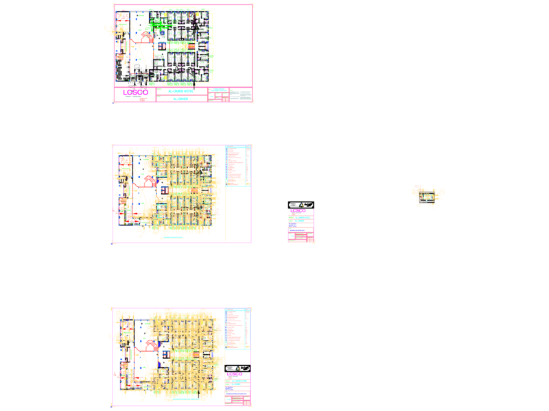
This drawing set presents detailed fire alarm system plans for four floors (15-18) of an ENGIE office building located at Paseo de la República 3617. This drawings illustrate the complete fire alarm detection network with precise component positioning and installation specifications.
Key Components:
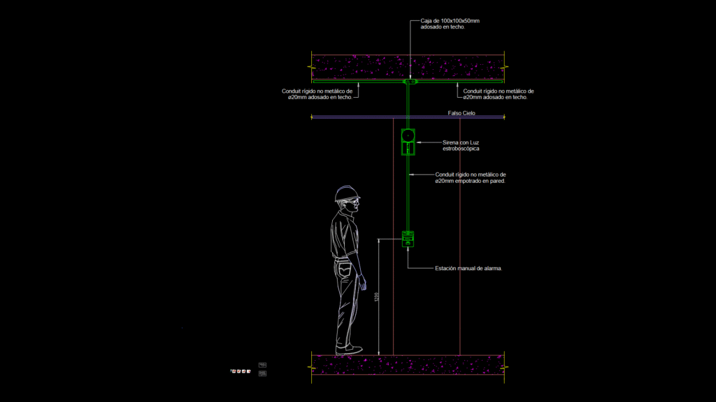
– Fire Alarm Control Panel (FACP) and remote annunciator (RFAP)
– Photoelectric smoke detectors throughout office spaces
– Temperature sensors in specific zones
– Manual pull stations at strategic locations
– Strobe/horn notification devices
– Flood/water sensors with supervision modules
– Valve monitoring modules (for flow and butterfly valves)
Installation Details:
– Ceiling-mounted devices use 100x100x50mm junction boxes
– 20mm (3/4″) EMT conduit for device connections
– Non-metallic 20mm conduit in walls for manual stations
– Specific mounting height of 1.80m for manual pull stations
– Detailed connection to suspended ceiling systems
The plans follow a standardized legend system across all floors, with precise device numbering and circuit identification. Each floor plan (1:100 scale) shows device locations coordinated with office layouts including meeting rooms, workstations, service areas, and communication rooms. The system interfaces with building mechanical and electrical systems through monitoring modules.
Notable design consideration: Device placement carefully accounts for office partition configurations while maintaining coverage requirements per applicable fire codes.