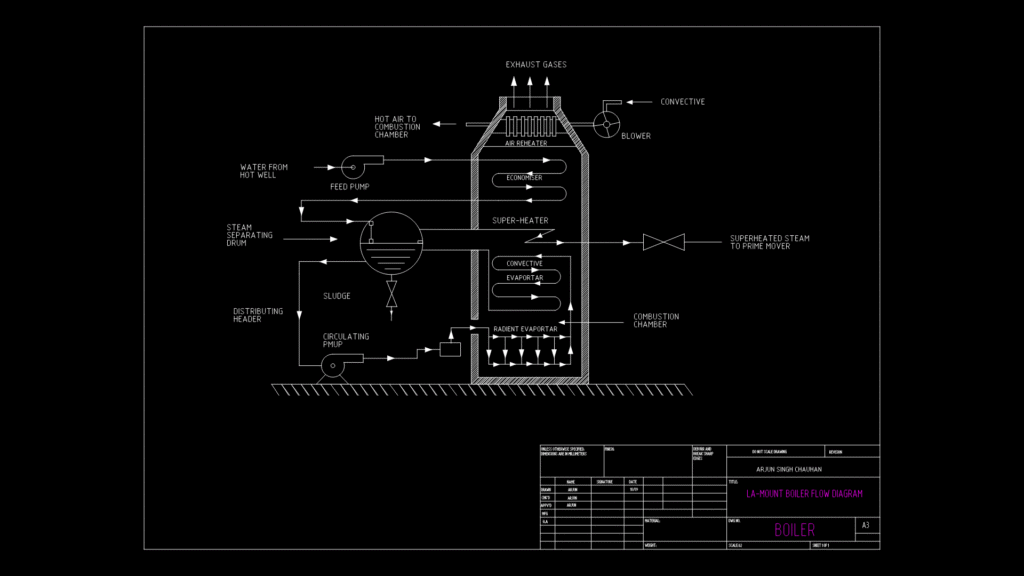
This technical diagram illustrates a comprehensive LA-Mount boiler system with integrated heat recovery components. This process flow shows the complete thermal cycle from initial water input to superheated steam output. Key components include a steam separating drum, feed pump, circulating pump, and multiple heat exchange elements including a super-heater, economizer, and two evaporator sections (convective and radient). The system utilizes hot combustion gases from an adjacent combustion chamber to generate superheated steam that feeds to a prime mover. Worth noting is the efficient multi-stage heat recovery design; exhaust gases pass through the air reheater while the radient evaporator captures waste heat at lower temperatures—a critical feature for maximizing thermal efficiency in industrial applications. The sludge removal pathway demonstrates practical consideration for maintenance and long-term operational reliability.
LA-Mount Boiler Process Flow Diagram with Integrated Heat Recovery