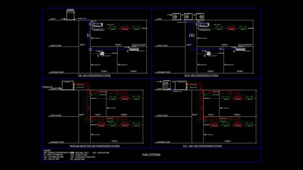
This MEP drawing presents a comprehensive HVAC system design for a three-story commercial building with roof mechanical space. The schematic illustrates four distinct air conditioning configurations: VRV (Variable Refrigerant Volume), Split, Package (Roof Top), and CCU-AHU systems. Each quadrant details the refrigerant piping paths, ductwork configurations, and equipment placement across the floors. The design incorporates strategic zoning with separate systems for Room 1, Room 2, Room 3, and toilet areas. Supply and return air ducts are clearly indicated with appropriate directional flows. Equipment specifications include outdoor condensing units on the roof level, various indoor units (cassette, high-wall split, FCU), VAV controllers, and thermostats. Condensate drain paths are directed to the nearest drain points. The drawing includes essential elements like mechanical shafts for vertical distribution, false ceiling locations, and control interfaces (wired thermostats and wireless remotes) – a practical approach that maximizes system flexibility while ensuring efficient climate control throughout the building.
Multi-System HVAC Schematic Plan for three-story Commercial Building