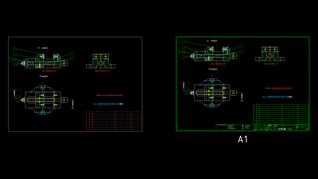
This technical drawing depicts a comprehensive machine vice assembly with detailed cross-sectional views. The drawing includes two critical sections (R-R and P-P) that illustrate the internal mechanism and mounting configuration. The vice features a movable jaw assembly with precision guide rails and a lead screw mechanism for accurate workpiece positioning. All components are dimensioned in millimeters with manufacturing tolerances adhering to H7/g6 fits for inserts up to 30mm, ensuring precise movement and clamping capability. The design incorporates threaded fasteners for secure assembly and what appears to be a swivel base mechanism for angular positioning flexibility. The cross-sectional views reveal the internal construction details including the jaw mounting surfaces and the central alignment mechanism. The vice includes features for bench mounting with strategically placed bolt holes. A notable design consideration is the symmetrical jaw configuration that allows for consistent clamping pressure distribution across workpiece surfaces.
Precision Machine Vice Assembly Detail with Cross-Sectional Views