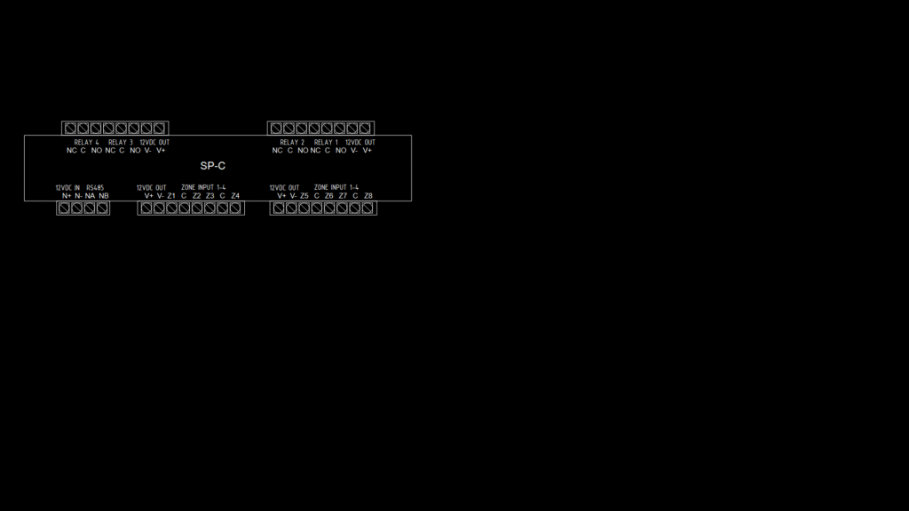
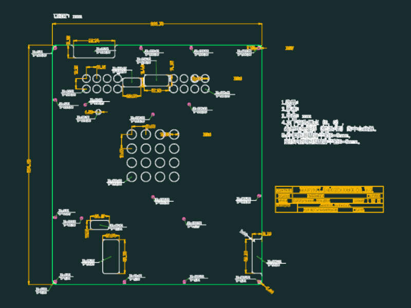
This CAD drawing illustrates the terminal connection layout for an SP-C series access control system controller. The diagram depicts a comprehensive wiring schematic showing 8 monitored zones across two reader ports (1-4 and 5-8), RS-485 communication interfaces, and multiple relay outputs. Key features include 12VDC power input/output terminals, bell circuit connections (B+/B-), and modem communication ports (T1i/R1i/R1o/T1o). The controller supports Wiegand interface card readers with connections for D0/D1, LED (L1), and buzzer (BZ) control. The drawing also references companion modules including SP-IO84 (input/output expansion), SP-PSU power supplies (4A and 8A variants), and SP-RDM2 (dual reader interface module). Terminal blocks are clearly labeled with voltage polarity markings (V+/V-) and relay contact configurations (NO/C/NC), facilitating proper field installation and troubleshooting.
SP-C Access Control System Block Diagram with Terminal Connections