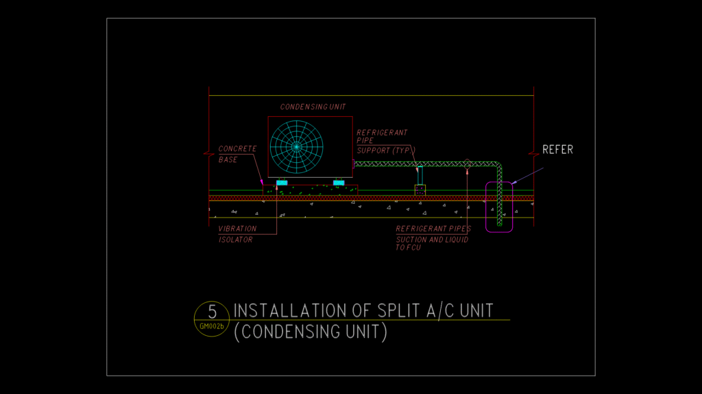
This detailed MEP drawing illustrates the standard installation configuration for split A/C condensing units. The drawing shows the condensing unit mounted on a concrete base with vibration isolators positioned underneath to minimize operational noise and vibration transfer to the building structure. Refrigerant piping routes are clearly delineated, including both suction and liquid lines that connect to the fan coil unit (FCU). The drawing emphasizes proper pipe support requirements with typical mounting brackets shown at regular intervals. Insulation specifications for refrigerant pipes exposed to exterior conditions include 13mm closed-cell tube insulation (Atlas-Foster 30-36 or equivalent), with proper adhesive application (Foster 85-20) and vapor barrier protection (Foster 30-35) to prevent condensation issues. The detail also references a P-trap configuration for condensate drainage, which is critical for proper system operation. This installation approach follows standard HVAC practice for split system installations where the condensing unit must be positioned with adequate clearance for airflow while maintaining accessible refrigerant line connections.
Split System Condensing Unit Installation Detail for HVAC Systems