VM3 Vertical Steam Engine Overview
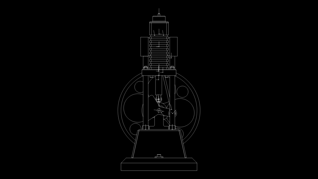
This detailed left elevation drawing depicts a small-scale vertical steam engine with classic proportions and mechanical precision. This drawing showcases the complete assembly with approximately 130mm width and 256mm height, rendered in millimeter scale.
Key Components:
• Cylinder Assembly: Positioned at the top of the engine with visible valve arrangement and finned cylinder design for optimal heat dissipation
• Connecting Rod System: Shows the rod linkage mechanisms that translate linear piston motion to rotational energy
• Flywheel: Large diameter wheel with multiple circular cut-outs for momentum maintenance and energy storage during operation cycles
• Base Mount: Tapered foundation with mounting provisions to secure the engine assembly
The drawing effectively illustrates the functional relationship between the valve gear, connecting rod, and crankshaft assembly. Notable is the finned cylinder design, suggesting this model incorporates adequate cooling for sustained operation. The proportions and configuration indicate this is likely a model or demonstration engine rather than an industrial-scale power unit, consistent with the VM3 designation.
This technical drawing would be valuable for machinists, model engineers, or steam enthusiasts looking to construct or understand the complete left-side mechanics of this particular vertical steam engine design.