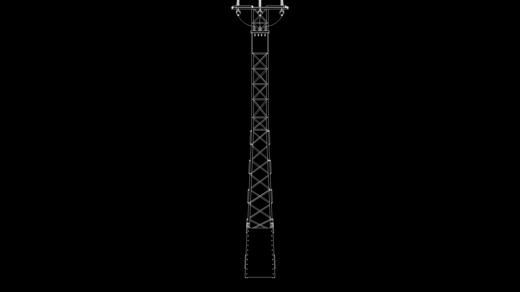
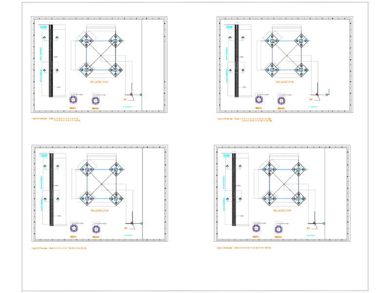
This detailed engineering drawing depicts a 220kV electrical transmission tower designed for integration with a single busbar scheme switchyard. The steel lattice structure features a tapered design with a reinforced base and cross-braced sections throughout the shaft. The tower incorporates specialized hardware at the apex for conductor attachment, including insulator string mounting points. X-bracing patterns provide structural rigidity while minimizing wind loading—a critical consideration for tall structures in exposed locations. The detailed fastener specifications (visible in the TORNILLERIA layer) comply with electrical infrastructure standards for high-voltage applications. The foundation appears to utilize a reinforced concrete base with anchor bolt connections. This drawing was prepared for tender purposes as part of switchyard layout documentation, with dimensions specified in millimeters according to metric standards.
220kV Transmission Tower Elevation Detail for Switchyard Integration