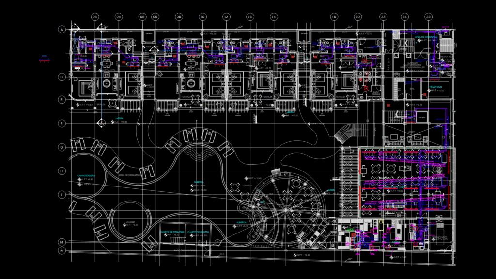
Comprehensive HVAC plan for the ground floor (+10.75m elevation) of Hotel Belo featuring a Variable Refrigerant Flow (VRF) system. The drawing shows refrigerant piping layouts, equipment placement, and condensate drainage systems throughout the facility.
Key System Components:
– Fan & Coil units (FC 4TVD models in various capacities: 18, 24, 30, 48 kBTU/h)
– Mini-Split units (MS 4TVW-07, MS 4TVD models)
– Outdoor condensing units (UC model designations)
– Refrigerant piping (liquid and gas lines ranging from 1/4″ to 1-1/2″ diameter)
– Condensate drainage system (PVC Schedule 40 pipe with 1% minimum slope)
– Digital thermostats positioned at 1.5m above finished floor level
Facility Areas Served:
The system serves multiple zones including restaurant (118 seats), bar, kitchen, lobby, reception, pool area, mechanical rooms, and service areas. Notable features include specific ductwork sizing with corresponding CFM values (ranging from 200 to 3,700 CFM) and detailed refrigerant branch distribution specifications.
The installation includes proper support systems for refrigerant piping with unichannel mounts, threaded rods, and expansion anchors as detailed in the installation specifications. All condensate drain lines utilize Schedule 40 PVC with proper slope for drainage.