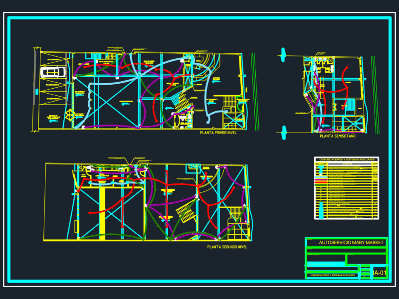
Comprehensive cable tray routing plan for a 5-story institutional building (Building No. 1) showing power and data distribution systems. The plan includes multiple floor layouts (basement, ground, 1st, 2nd and roof levels) with a total building footprint of approximately 550 m².
Cable Tray Specifications:
– Hot-dip galvanized cable trays in various widths (100mm, 200mm, 300mm, 400mm, 500mm, 600mm)
– Separate routing for power (lower position) and data cables (upper position)
– T-connections, 90° turns, and 4-way connection elements
– Sub-floor cable channels and covered cable trays in specific areas
System Features:
– Vertical shaft integration for floor-to-floor connectivity
– Coordinated pathways around architectural elements (stairs, columns, doorways)
– Clear hierarchy between power and low-voltage distribution systems
– Strategic placement to accommodate the building’s structural layout with dimensions of 24m × 4.5m
The drawing includes equipment legends identifying connection types and installation notes for the cable management system implementation.