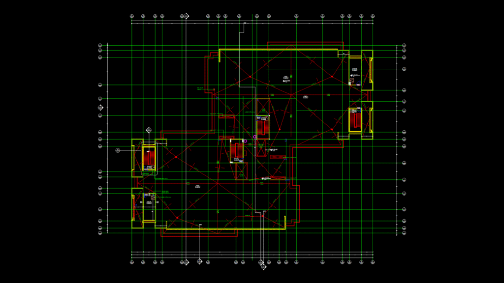
This roof plan for a call center building (sheet AE103) depicts a commercial facility with multiple integrated systems. The drawing shows a 1:100 scale roof layout with a robust drainage system utilizing J.R. Smith 1005-04 roof drains strategically positioned for 1% slope drainage toward a central ridge at elevation 108.400. Four stairwell access points (labeled Stair 01-04) provide roof egress, complemented by wall-mounted metal ladder access. The plan includes mechanical, HVAC, and, in essence, electrical shafts, with a provisional elevator shaft. Construction utilizes concrete block walls (both solid and hollow) with specified fire ratings (1-2 hours). The roof parapet rises to elevation 108.500, while the finished floor level sits at 108.000. The design incorporates designated storage areas and safety railings along perimeter edges. Drawing coordinates with other architectural sheets through referenced section markers and critical elevations.
Commercial Roof Plan with drainage System and Access Points