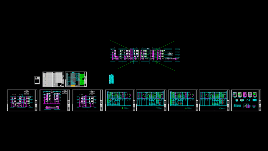
Substation Overview
This drawing details a 10kV/0.4kV electrical substation located in the basement (B1) of a laboratory building. The substation features four 1250KVA dry-type transformers with epoxy resin cast, low noise, low loss specifications, and forced ventilation systems with IP3X protective enclosures.
Key Technical Components
– High Voltage Equipment: 10kV medium-voltage switchgear with radial supply from two different high-voltage circuits
– Transformers: Four 1250KVA dry-type units with protective features including high-temperature alarm and trip functions
– Low Voltage System: Single bus-bar sectional operation mode with drawer-type low-voltage distribution cabinets
– Cable Trench: 0.8m deep for cable management
– Room Clearance: 3.7m net height for equipment maintenance and safety
Distribution System Specifications
The power distribution system uses TN-S grounding configuration with dedicated PE lines for all socket circuits and 30mA leakage protection. Lightning protection is designed as Category B with SPD (Surge Protection Device) rated for 60KA (8/20μs) in distribution rooms. The facility requires a combined grounding system (lightning protection, electrical equipment protection, equipotential bonding, and anti-static) with resistance not exceeding 1 ohm.
Tier-2 load devices (emergency lighting, fire control center, fire fans) have dual power sources with automatic switching capability. The lighting system employs high-efficiency T8 fluorescent fixtures with electronic ballasts (CosPhi≥0.9). Power feeds to critical fire safety equipment use fire-resistant cables (ZCN-YJV-1KV) with appropriate cable management systems.