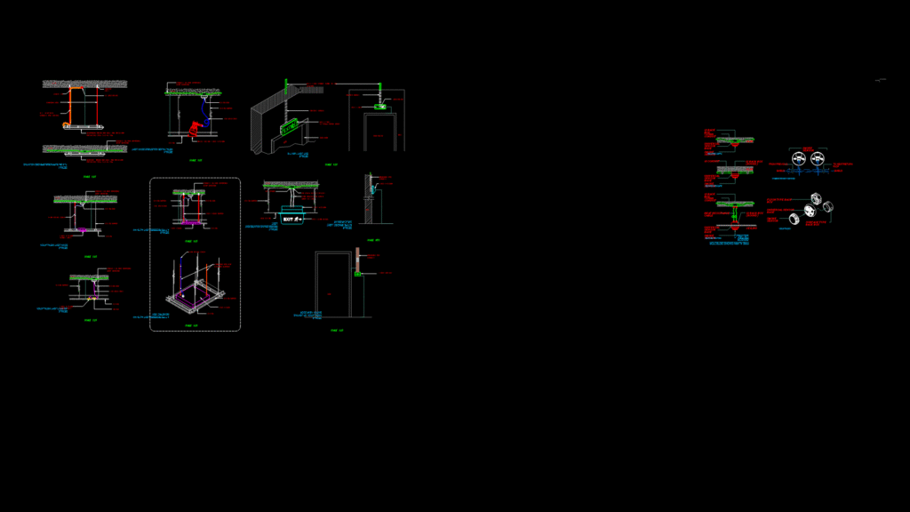
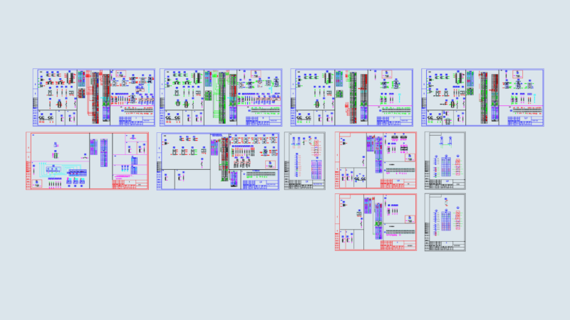
This comprehensive fire safety detail drawing includes multiple installation configurations for smoke and heat sensors within a building environment. The drawing features detailed sections showing ceiling-mounted smoke detectors, heat sensors, and universal sensor bases with their associated wiring diagrams and mounting details. Key components include fire-rated cable pathways, GI junction boxes, and conduit specifications for proper installation. The drawing illustrates various mounting methods including surface mounting, flush mounting, and ceiling mounting options with appropriate back boxes. Installation details show the relationship between sensors and building elements such as ceilings, walls, and conduit systems. The drawing also includes exit light installations (positioned 200mm above doors) and their connection to the fire alarm control panel. Notable is the shielded cable specification for reducing electromagnetic interference in these sensitive detection circuits—a critical consideration for preventing false alarms in commercial installations. All components are designed to integrate with a centralized fire alarm system with proper return paths to the control panel.
Fire Alarm System Detail Drawing with Smoke and Heat Sensor Installation