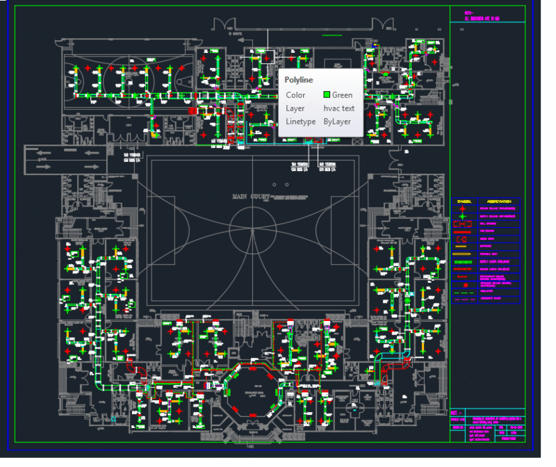
This detailed generator room floor plan (drawing TC-MEP-DT-103) illustrates a comprehensive MEP coordination layout at scale 1:30. The room features a diesel generator with dedicated intake and exhaust systems including sand trap louvers (3500x1300mm @ 14176 L/s), muffler, and smoke pipe. Ventilation is designed with proper airflow parameters of 5.0 m/s through the intake louver (2000x1500mm) and exhaust louver (1500x1700mm). The facility includes a foam fire suppression system with associated piping (Ø25mm and Ø50mm), control panel, and water motor alarm gong. Cable management is provided via 350mm HDGI cable tray mounted at BOT+3950mm. Room elevation is at +3.40m FFl with drainage infrastructure incorporating a 2000x2000x2200mm sump pit. The design shows careful consideration of ventilation requirements for heat dissipation and exhaust management, essential for preventing equipment overheating during generator operation.
Generator Room MEP Coordination Floor Plan with Ventilation System