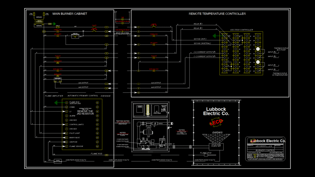
Comprehensive electrical control schematic for a 1 million BTU industrial burner system featuring safety interlock circuitry and temperature regulation components. The diagram integrates multiple subsystems:
Main Components:
– UDC3500 temperature controller with dual thermocouple inputs and mA output for modulation
– Automatic primary control with flame amplifier for flame safety monitoring
– Pilot and main gas valve controls with pressure switch interlocks
– 6000V ignition transformer for burner ignition
– Modulating valve and motor assembly for precise temperature regulation
Safety Features:
– Flame rod detection system with sensor ground
– Air safety pressure switch (Dwyer)
– Fan interlock relay integration
– Control limits with emergency shutdown capability
– Low pressure monitoring (0-30 PSI gauge)
The system operates on 120VAC with a 2A protection circuit for control components and includes specific pressure limitations (pilot valve rated for 15 PSI, main valve for 25 PSI). Critical installation note: JR2 resistor must be removed during implementation. The drawing includes both electrical connections and a simplified gas train layout with pressure regulation components.