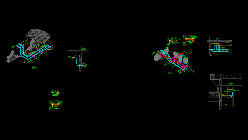
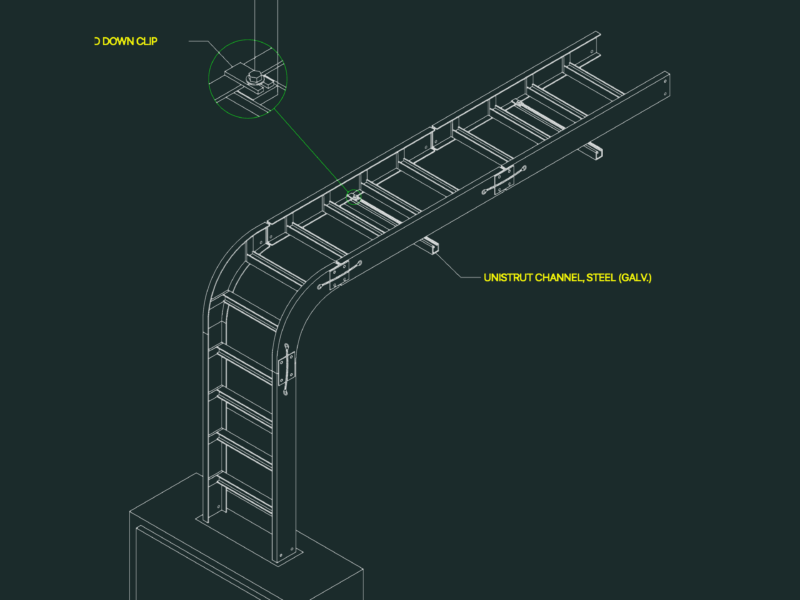
This detial drawing illustrates the installation configuration for cable ladder systems in an industrial facility, featuring both 500mm and 300mm width cable trays. The drawing includes multiple sectional details showing the mounting methodology between floors at EL.+6.300 (second floor slab) and EL.+2.700 (ceiling height). Key structural components include U-75x50x5t steel supports, C-channel 100x50x2.3t brackets, and 1/2″ diameter rod hangers for overhead suspension. Communication raceways (150x50mm with cover) run parallel to the main cable trays at specific heights (EL+4.400, EL+4.100, EL+3.800). Wall penetration details show properly specified openings with elevation markers at H=3,050mm, H=4,350mm, and H=5,030mm. The support system is engineered to accommodate corridor pathways with proper clearances for maintenance access. Each support detail is drawn at appropriate scales (1:10, 1:20, 1:25) to ensure precise implementation during construction.
Industrial Cable Ladder Support Detail Drawing with 500mm Tray Width