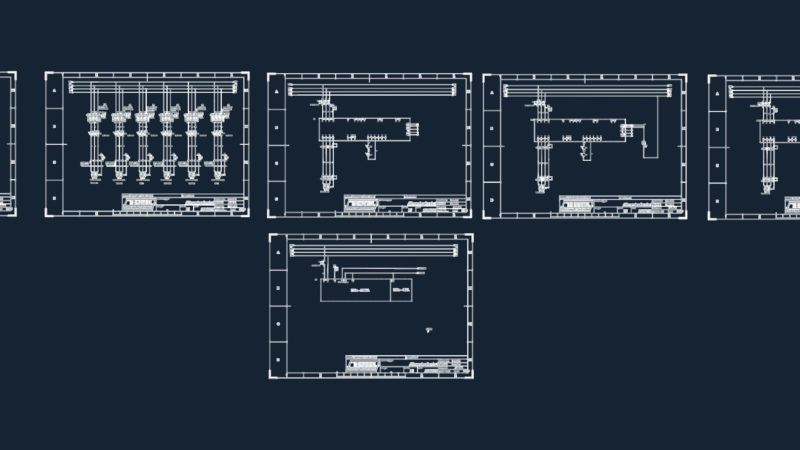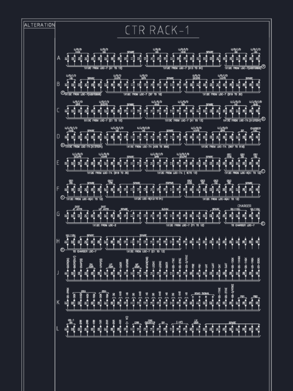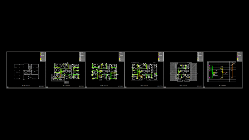
Comprehensive telecommunications infrastructure plan for a 5-level building spanning from basement to roof, with a total area of approximately 2,500 m². The drawing features detailed CAT6 UTP HF cable routing paths, RG6/U6 HF coaxial cable pathways, telephone lines, and data connections across all floors. The system is centralized around a 19″ 32U rack cabinet equipped with 48-port patch panels (4 units) and switches (4 units). The infrastructure includes:
Key Components:
– 164 CAT6 UTP data outlets
– 41 wall-mounted data outlets on ground floor
– 48 data outlets on first floor
– 50 data outlets on second floor
– 24 access points strategically positioned throughout the building
– Fiber optic backbone (4-core SM/FO) connecting IT rooms
– Hybrid IP digital telephone system with analog/digital connections
– Television distribution system with 10/8 multiswitch and satellite dish
The plan includes detailed riser diagrams showing vertical pathway connections between floors through designated shafts. UPS power supplies are specified for active equipment protection. All equipment for CCTV, public address, data, and telephone systems are consolidated in the same cabinet for efficient management.