Plans bridge complete project – Project of a girder slab – architectural plans; structure; false bridge formwork and details .
Drawing labels, details, and other text information extracted from the CAD file (Translated from Spanish):
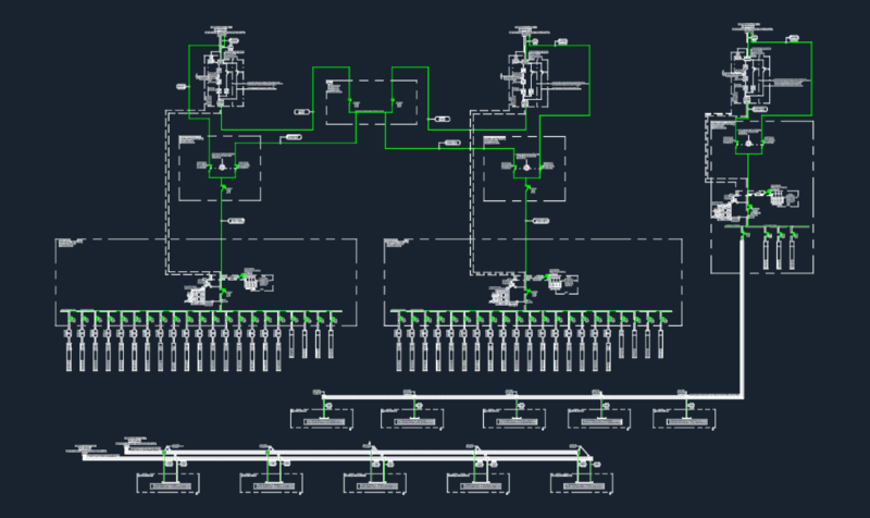
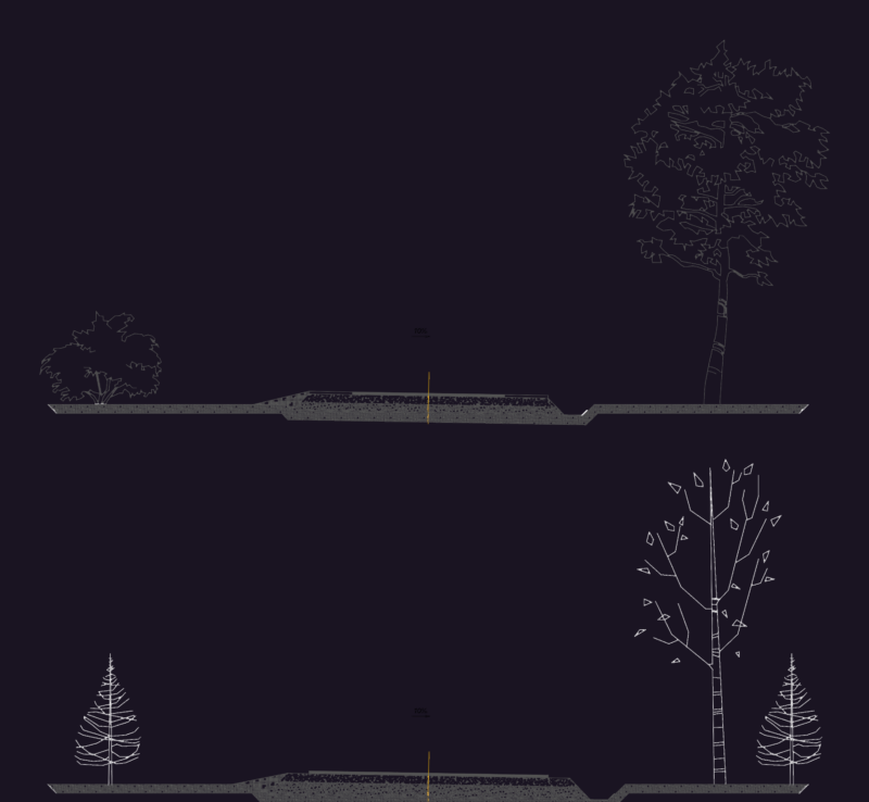
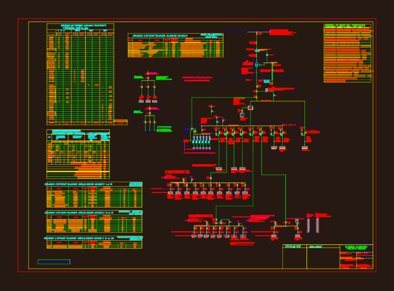
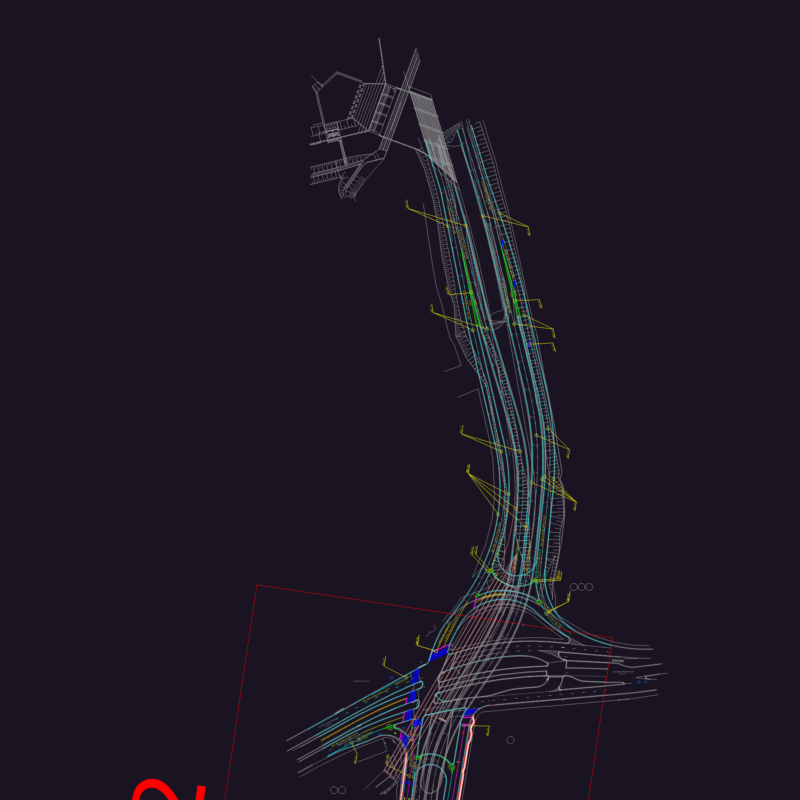
variable height, gravel filter, expansion joint, metal railing, right abutment, left abutment, lateral elevation, general floor, filling area, sub razante, flooring, river, specifications, concrete:, footing, abutments, runway level, plant drain detail, drainage detail, wings, front elevation right abutment, right abutment foundation, front left abutment elevation, left abutment foundation, frontal elevation, technical specifications, – left foundation, formwork surface, – right abutment, – elevation , – left elevation, concrete volume, – parapet, maximum pressure transmitted to the ground, – parapets, in order to restrict as much as possible segregation of the material and work with a more homogeneous mixture, exceed the tolerances allowed. so that during the emptying there are no displacements that, notes, non-metallic coatings that may adversely affect its adhesion capacity., Cut middle section, right abutment, section, middle section, left abutment, minimum, struts, brace, filling at ground level, perforated pvc, longitudinal profile, false bridge, slabs, slab resting on the abutment, slab length, distribution of struts in plant, bridge light, false cross section bridge, the ing. Resident must contemplate the use of the proposed structure. being, the definitive structure verified in work and approved by the ing. inspector., minimum admissible efforts of the wood, river bottom, minimum waters, maximum waters, extraordinary waters, cut aa, mobile support, fixed support, joints, expansion, est., longitudinal cut a – a, lower support plate , upper support plate, running surface, upper reinforcement, lower reinforcement, floor, super-structure specifications, concrete, anchor length, covering, beam, design overload, upper slab, lower slab, others, minimum overlap to consider, box of standard hooks in rods, of corrugated iron, finish in standard hooks, concrete with the dimensions, which will be lodged in the longitudinally, in beams, and foundation slab, should, the reinforcing steel used , shown., specified in the table, note, parapet, metal expansion joint, slab, cross section, main beam reinforcement arrangement, diaphragm reinforcement arrangement, slab reinforcement arrangement, detail day fragma aa, section cc, section x – x, cut aa, bb cut, creep limit, tensile strength, expansion joint specifications, rolled steel, weldability, easy weldability, quality and norm, railing specifications, railings seran painted black ,, tube, paint, oil paint, profile, front, diaphragm, tread folder