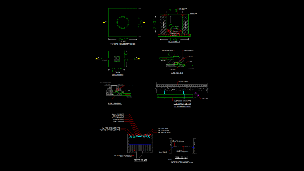
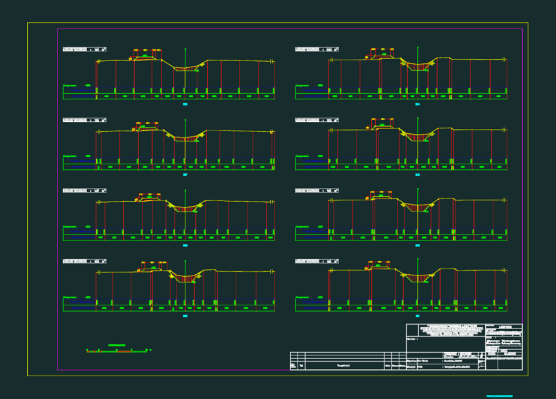
This technical detail sheet provides comprehensive construction specifications for various plumbing components used in wastewater systems. This drawing includes plan and section views of a typical 3′-6″ square sewer manhole with brick masonry construction, cast iron cover, and PCC benching (1:2:4). A 2′-0″ gully trap detail shows inlet/outlet pipe configurations with stainless steel grating and uPVC P-trap connections. The P-trap detail illustrates proper installation with PCC foundation (14 MPa) and connection to manholes. The clean-out detail depicts suspended sewer pipe installation with proper end cap termination at pipe starts. The duct plan shows a comprehensive MEP layout including 4″ soil pipes, 2″ vent pipes, 4″ waste pipes, and multiple hot and cold water lines (ranging from 40mm to 110mm diameter). The metal grating detail includes specifications for removable angle iron frames (1½” x 1½” x 1¼”) with M.S. flats at 2″ centers. All components conform to standard plumbing practices with careful consideration for proper drainage slopes and watertight connections throughout the system.
Plumbing System Detail Sheet: Manholes, Traps, and Duct Sections