Designs CAD
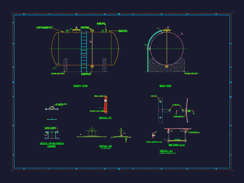
RELIEF VALVE
Concrete wall, concrete cover, handle
\A1;1.00 \A1;0.80 \A1;0.10 \A1;0.10 \A1;0.50 \A1;0.10 \A1;0.10 \A1;0.10 \A1;0.90 \A1;0.10 \A1;0.10 \A1;0.90 \A1;0.90 \A1;0.05 \A1;0.05 \A1;0.05 \A1;0.60 \A1;0.05 \A1;0.10 \A1;0.05 \A1;0.60 \A1;0.05 \A1;0.10 \A1;0.05 \A1;0.05 \A1;0.60 \A1;0.10 \A1;0.10 \A1;0.05 \A1;0.60 \A1;0.60 \A1;0.90 \A1;0.06 \LVÁLVULA DE PURGA 5 5 MURO CONCRET. 5 5 5 5 5 5 TAPA DE CONCRETO 5 5 5 5 5 5 5 5 \fTimes New Roman|b0|i0|c0|p18;PLANTA 5 5 5 5 5 5 5 \fTimes New Roman|b0|i0|c0|p18;A 5 5 5 5 ASA 5 @ 0.10m ACERO 3/8″ \fTimes New Roman|b0|i0|c0|p18;A 5 5 5 ASA \fTimes New Roman|b0|i0|c0|p18;TAPA 5 \fTimes New Roman|b0|i0|c0|p18;CORTE A-A 5 1 2 3 4 5 1 = TUB. P.V.C. DE PURGA 2 = TRANSICION P.V.C. 4 = TEE P.V.C. 3 = VALVULA DE COMPUERTA 5 = TUB. DE LA LINEA DE CONDUCCION 1 4 5 2 3
or get unlimited access from $7/mo