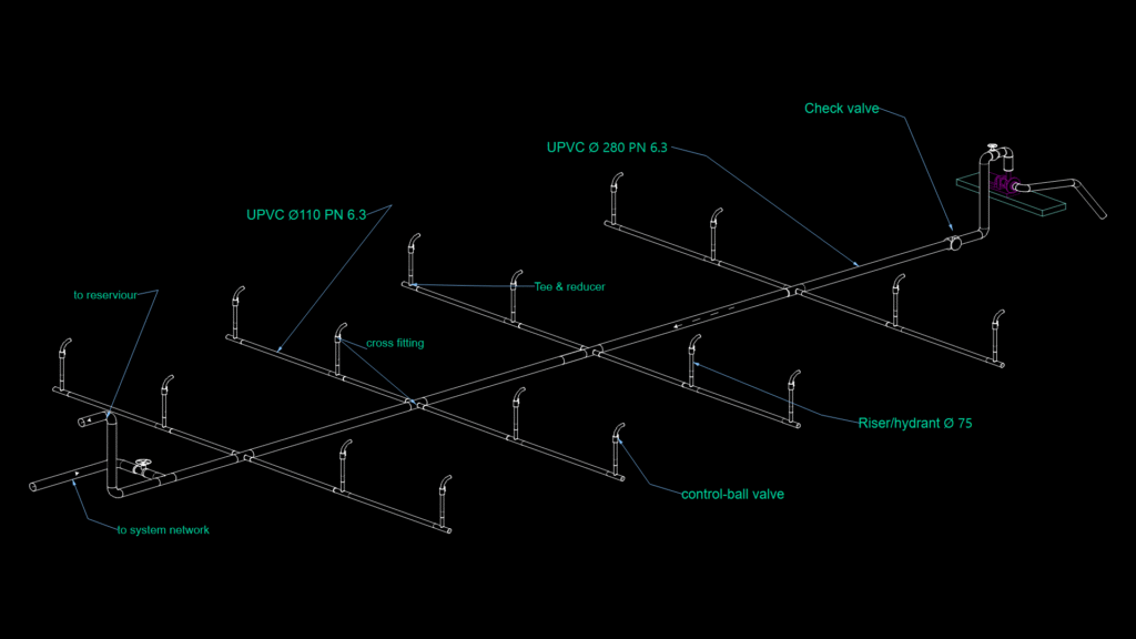
Isometric diagram of a pressurized UPVC pipe distribution network with integrated hydrant system. The primary supply line uses Ø280mm PN6.3 UPVC pipe, branching into a grid network with Ø110mm PN6.3 UPVC secondary lines. Vertical risers/hydrants of Ø75mm are strategically positioned throughout the network. Key components include:
Control Elements:
– Check valve on main supply line
– Control-ball valves at hydrant bases
– Connections to system network and reservoir
Junction Components:
– Cross fittings at primary intersections
– Tee fittings with reducers at branch connections
The pressure rating of PN6.3 indicates the system is designed for water distribution with maximum operating pressure of 6.3 bar. The network layout ensures redundant flow paths for improved reliability during firefighting operations.