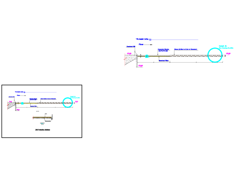
Cross-section and lateral pressure diagram for a reinforced concrete retaining wall with a total height of 4.55 meters. The drawing shows a tapered wall profile with a 0.25m top width and a 0.40m base width, partitioned into three segments for structural analysis.
The technical layout includes earth pressure distribution markers for force vectors (F1, F2, F3) and pressure points (p1, p2, p3) across the vertical face. It is used for verifying stability, sliding resistance, and overturning moments in road containment and civil engineering infrastructure. All dimensions are in metric units. Cálculo de muro de contención.