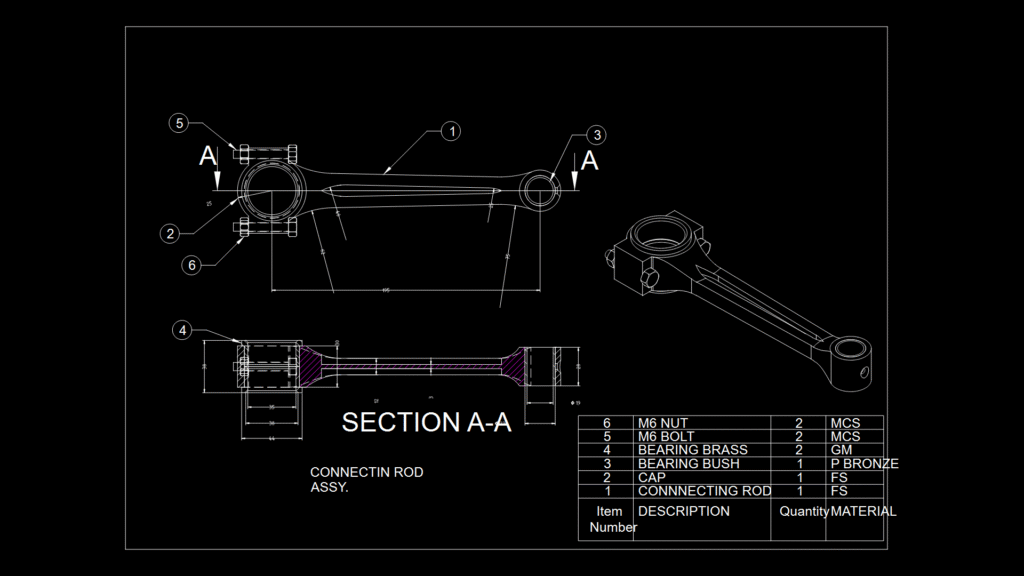
This technical drawing depicts a complete engine connecting rod assembly with detailed cross-sectional views. The assembly consists of six primary components: the main connecting rod (FS material), cap (FS material), bearing bush (phosphor bronze), bearing brass inserts (GM material), and fastening hardware (M6 bolts and nuts, MCS material). The drawing features a comprehensive Section A-A view that reveals the internal bearing configuration with dimensional specifications. Key measurements include a 19mm diameter bearing bush and a 22mm outer dimension. The assembly design employs a classic split-cap configuration secured by M6 bolts, allowing for maintenance access to the bearings. The bearing surfaces utilize brass and phosphor bronze materials for their low-friction properties and durability under high-temperature, high-pressure engine operating conditions. The connecting rod body features precise radii transitions to minimize stress concentration points where fatigue failure typically occurs in engine applications.
Engine Connecting Rod Assembly Section drawing with Brass Bearings