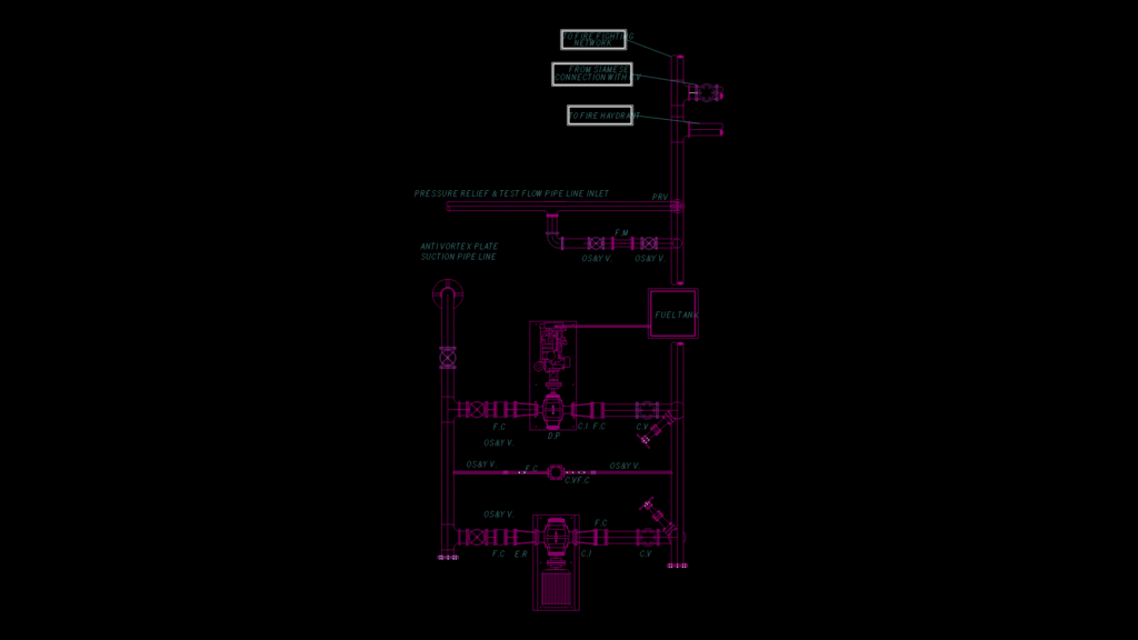
This detailed schematic depicts a comprehensive fire protection pump system with multiple redundant pumps and control mechanisms. This system features a main electric fire pump, a diesel backup pump, and a jockey pump for pressure maintenance. Key components include OS&Y (Outside Stem & Yoke) gate valves throughout teh system for isolation, check valves (C.V) to prevent backflow, and a pressure relief valve (PRV) with test flow piping. The suction line incorporates an anti-vortex plate to prevent air entrainment and ensure efficient pump operation. The system connects to both building sprinkler networks and external fire hydrants, with a dedicated siamese connection for fire department access. A fuel tank supports the diesel pump operations during power outages, ensuring system reliability in emergency conditions. The piping configuration includes critical flow control devices, pressure regulation, and proper drainage points (D.P) for system maintenance. This arrangement complies with NFPA 20 standards for fire pump installations, prioritizing redundancy and fail-safe operation for life safety applications.
Fire Fighting Pump System Schematic with Electric-Diesel Redundancy