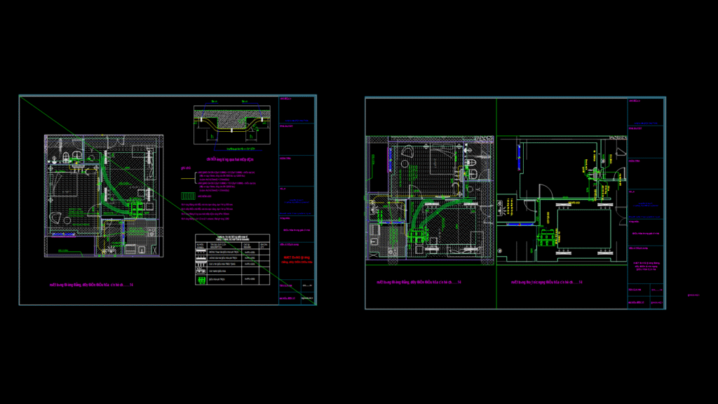
Detailed HVAC mechanical engineering plan for apartment unit CH14 showing the layout of air conditioning refrigerant piping, electrical connections, and condensate drainage systems. This drawing includes:
System Components:
– Wall-mounted air conditioner (12,000 BTU) in bedroom area
– Ceiling-mounted concealed air conditioner (22,000 BTU) with ductwork for living/dining area
– Two outdoor condensing units (one for each indoor unit)
– Supply and return air diffusers for the ceiling unit
Technical Specifications:
– Refrigerant piping: Copper tubes with 19mm insulation
• Living area unit: Ø9.5/15.9mm copper pipes, length 4.46m
• Bedroom unit: Ø6.4/9.5mm copper pipes, length 7.90m
– Condensate drainage: Ø21mm embedded floor pipes, Ø60mm drainage holes
– Electrical wiring: 4(1×2.5)+E(1×2.5) mm² for both units
– Ductwork: Ø200mm flexible ducts with lengths of 5.55m, 3.71m, and 2.69m
The plan includes a detail for refrigerant piping crossing beam edges and specifies mounting heights for indoor units (H=FFL+2550). The drawing provides essential information for HVAC installers regarding piping routes, electrical pathways, and condensate drainage solutions.