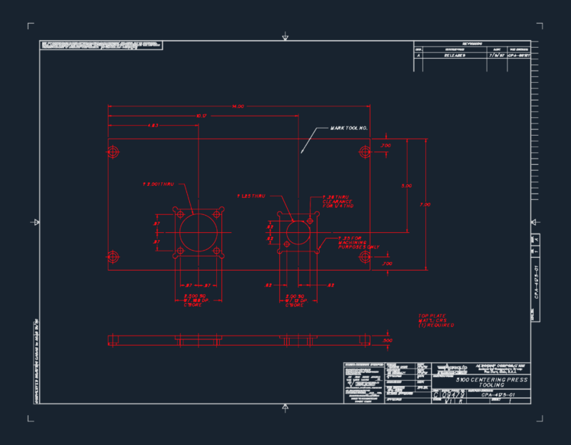
Component Overview
This engineering detail drawing depicts a precision-machined bracket component for industrial applications. This drawing features multiple views including a primary plan view, detailed section A-A, and an isometric representation to clarify the 3D form.
Key Specifications:
– Manufacturing according to ISO 2768-m general tolerance standards
– Surface roughness requirements of 1.6 Ra for critical surfaces
– 6.3 Ra for non-critical surfaces
– (4x) notation indicates four identical mounting holes
– Positional tolerancing of +2.0/-0.5 mm for critical features
Design Features
The component appears to be a mounting bracket with angled surfaces and precision-drilled holes. The section view reveals the internal geometry, including what appears to be threaded inserts or mounting points. The angled chamfers (shown in the lower left view) are precisely defined and critical to the component’s function, likely for proper alignment during assembly.
The drawing follows first-angle projection standards (explicitly noted in the title block) and is produced to ASME Y14.5M-1994 dimensioning and tolerancing standards. The GROB manufacturer identifier suggests this is likely an automotive or industrial machine component designed for precision applications.