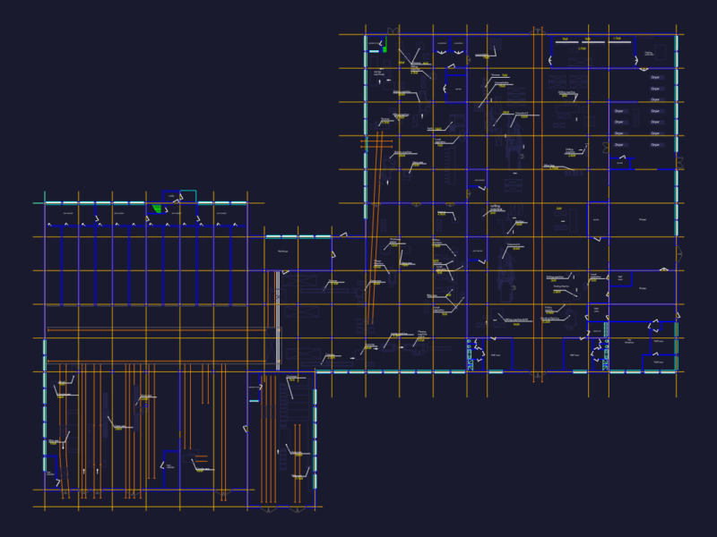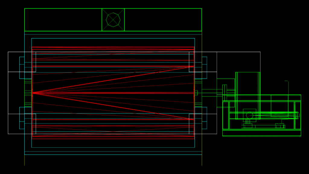
This technical drawing illustrates a shell and tube heat exchanger assembly with integrated control mechanism. The drawing incorporates both plan and sectional views highlighting the following components:
**Main Assembly Features:**
– The main body consists of a horizontal shell with internal tube arrangement, identified by parallel lines in red showing the heat transfer surface area
– Dual-ended design with connection points visible at both ends
– Shell assembly dimensions approximately 4100 x 2200 mm based on drawing bounds
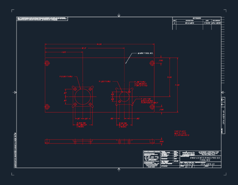
The detail view (right side) depicts the TopWorks control assembly that includes:
– Mounting flange connection to the main vessel
– Actuator mechanism with cylindrical components
– Control linkage system with mechanical interfaces
The drawing utilizes multiple layers including dedicated ones for equipment (EQP), steel components, and topworks control elements. The 3D solid entities (24 total) represent the primary mechanical components, while the structural framework is defined through multiple centerlines and boundary elements.
This assembly demonstrates industrial process equipment design with particular attention to the integration between the thermal exchange vessel and its control mechanisms. The drawing would typically be used for fabrication planning, maintenance documentation, or installation reference in industrial processing applications.