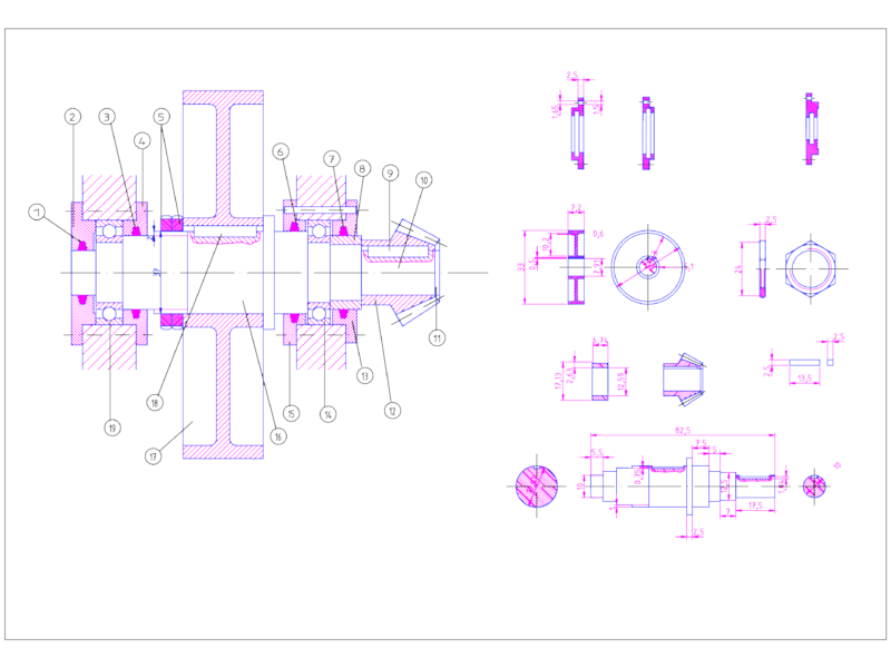
Mechanical linkage mechanism featuring three pivot points with mounting holes configured in a specific geometric arrangement. This design includes circular mounting flanges connected by curved contour paths, with precise angular measurements of 45° and 90° indicated for the movement arcs. The overall footprint measures 215mm in length, with a height of 150mm. Each pivot point features concentric circles indicating bearing or bushing interfaces. The central pivot features a larger diameter opening than the two end pivots, suggesting different load capacities or functional requirements. The smooth curved profiles connecting the mounting points are designed to optimize stress distribution during operation while maintaining clearance for full range of motion.
Mechanical Linkage Mechanism Detail Drawing with Angular Pivot Points