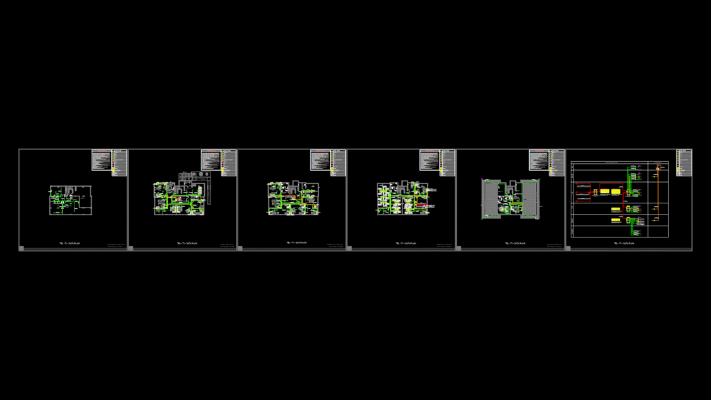
Comprehensive Low-Voltage Systems Layout
Complete telecommunications infrastructure plan for a multi-level educational facility (Building No. 2) spanning five floors (basement, ground, first, second, and roof levels). The drawing details CAT6 UTP HF cabling pathways, equipment locations, and network topology with the following key components:
Network Infrastructure:
– Server room with 42U rack cabinets (600x800mm) containing patch panels and switches
– Multiple 15U distribution cabinets (600x600mm) at strategic locations
– Structured cabling system using CAT6 UTP HF cables (minimum 350MHz)
– Fiber optic backbone (8-core SM/FO) connecting to adjacent buildings
– Wall-mounted data, telephone, and TV outlets throughout all floors
– Access points for wireless network coverage
Equipment Specifications:
– Core network switches with 48-port configurations
– PoE switches for device powering
– Patch panels for termination
– Multiswitch system for TV distribution from rooftop satellite dish
– UPS power backup for critical systems
The plan includes detailed riser diagrams showing vertical pathway connections between floors and horizontal distribution on each level. Cable pathways utilize cable trays with properly secured bundles every 200cm. The design follows telecommunications industry standards with specific provisions for testing, labeling, and documentation.