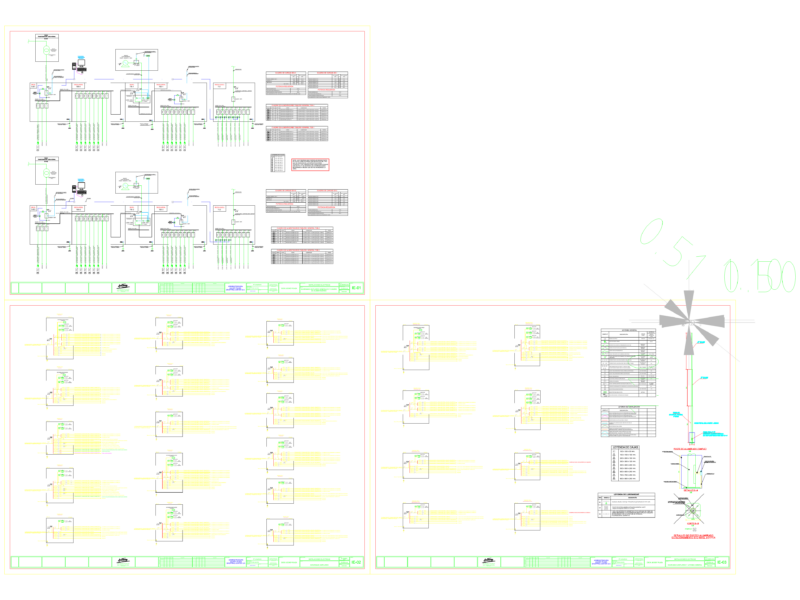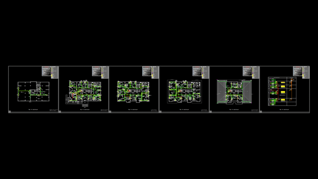
Comprehensive telecommunications infrastructure plan for a 5-level institutional building (basement, ground floor, first floor, second floor, and roof) with a total area of approximately 2,500 m². The drawing details data, telephone, and TV distribution networks throughout the facility.
Network Infrastructure Components:
- Four rack cabinets strategically positioned throughout the building (one 42U 600x800mm main cabinet and three 15U 600x600mm distribution cabinets)
- CAT6 UTP HF cabling for data and telephone distribution
- RG6/U6 HF coaxial cabling for TV distribution with multiswitch system
- Fiber optic backbone using 4-core and 8-core SM/FO cables
- Network equipment including 48-port PoE switches and patch panels
Outlet Distribution:
The plan incorporates various outlet types including data ports, telephone jacks, TV outlets, HDMI connections, and combination outlets. Distribution is optimized per floor: basement (27 ports), ground floor (49 ports), first floor (42 ports), second floor (22 ports), and roof level (29 ports).
All active network equipment is specified for UPS power backup, and cable pathways are designed for overhead cable tray installation (marked as “TAVADA”). The design includes provisions for wireless connectivity via strategically placed access points throughout the facility.