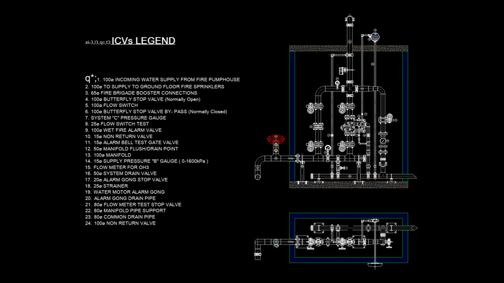
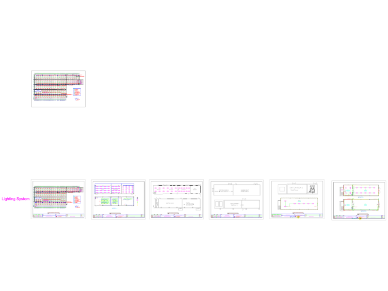
This detailed engineering drawing depicts an OH3 (Ordinary Hazard Group 3) fire sprinkler control valve assembly with comprehensive component identification. The drawing shows a complete installation configuration with 100mm incoming water supply from the fire pumphouse and distribution to ground floor fire sprinklers. Key components include butterfly stop valves (normally open/closed configurations), a wet fire alarm valve, flow switches, pressure gauges (0-1600kPa range), and multiple drain points. The system features a 65mm fire brigade booster connection, 25mm flow switch test line, and water motor alarm gong with associated piping. The installation includes critical safety elements like non-return valves (100mm and 15mm), strainers, and a dedicated 80mm flow meter test circuit. The manifold arrangement demonstrates proper valve sequencing and spacing required for NFPA-compliant installations, with particular attention to the test and drain arrangements needed for regular system verification and maintenance procedures.
OH3 Fire Sprinkler Control Valve Assembly Detail Drawing