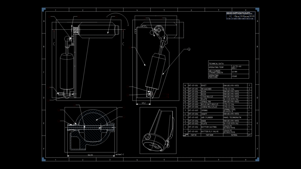
This detailed technical drawing illustrates a pneumatic engine brake assembly featuring multiple views of the complete mechanism. The system utilizes a 40mm stroke length air cylinder operating at 6 BAR pressure within a -20 to +80°C temperature range. The assembly includes a butterfly valve mechanism (part MT-07-001) connected to a bottom casting (MT-07-002), with actuation delivered through a central shaft and spring arrangement. Multiple section views reveal the internal components, including the critical butterfly valve that regulates exhaust flow during braking events. The drawing provides complete assembly information through a comprehensive BOM (Bill of Materials) containing 16 components with standardized part numbers, materials (primarily EN (BS:970-1955) steel variants), and quantities. Cross-sectional view C-C (164.58mm width) shows detailed internal geometry of the valve housing, while auxiliary views illustrate the mounting arrangement and actuation linkage. This pneumatic brake system is designed for heavy-duty applications where controlled engine braking is critical for vehicle control during deceleration.
Pneumatic Engine Brake Assembly Technical Drawing with Cylinder