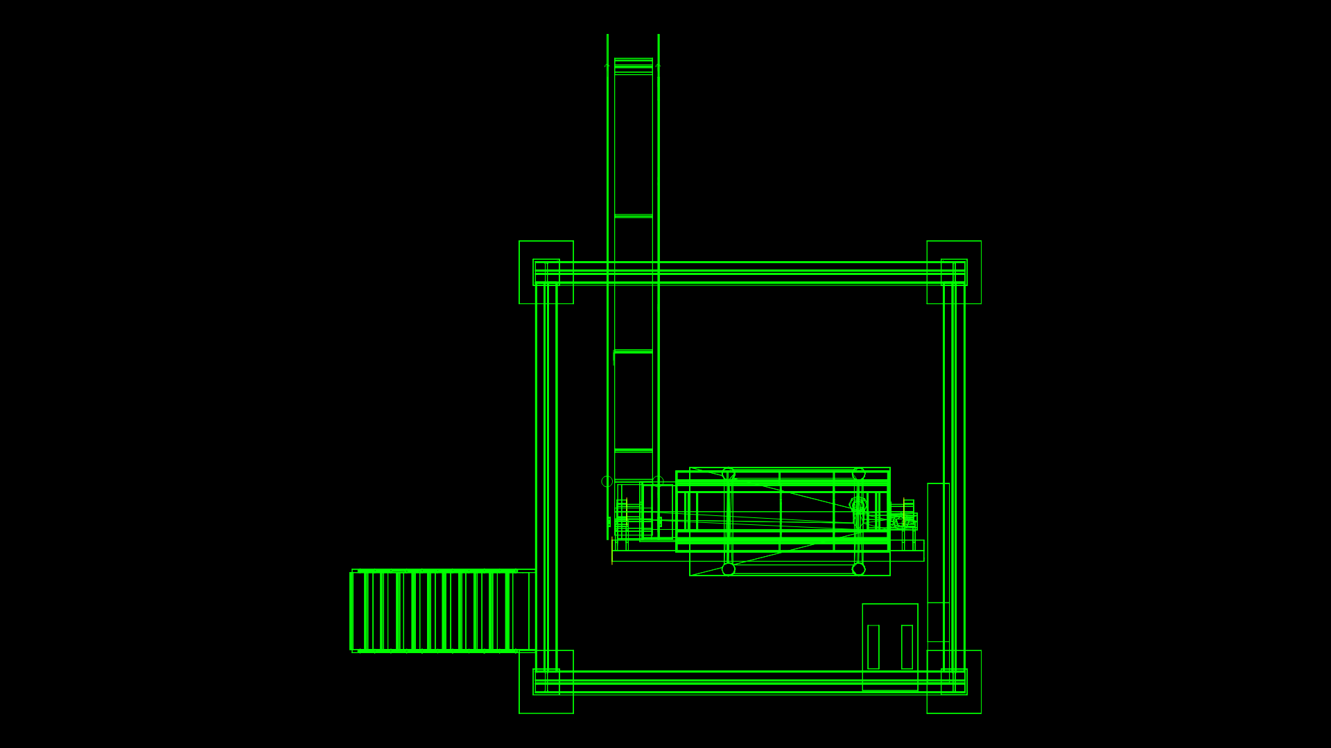
Bag Filter DWG Block for AutoCAD
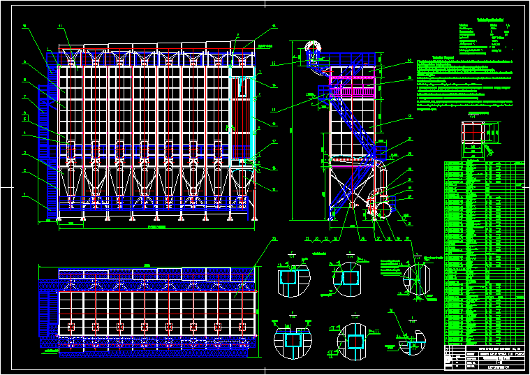
Filter air dusting microscopic solid particles
Drawing labels, details, and other text information extracted from the CAD file:
assembly, inlet of air with dust, outlet of cleaned air, before installing bottom hole, flat steel, around inner side of plates., then weld bottom hole plate, on the flat steel and weld them., flange at discharging opening, air volume:, total filtering area:, bag room number:, rooms, filtering bag number:, pcs, gab size:, equipment, filtering air speed:, max. temperature of air with dust at inlet:, discharging density of outlet:, ash filtering method: air, technical specification list, top plate, outlet of cleaned air, upper hole plate, top plate, inner corridor, flat steel, bottom side seperating plate, technical, the level should be decided by the technical condition. all the rods should be on the same horizontal surface with permitted error and the vertical error should be under, some suitable measure should be taken when lifting the equipment to prevent assembly from distorting., all the welding line should be well sealed. and asbestos wire or rubber pad should be added to flange connection., discharging pipes and fan should be installed on site. after installing airing groove and bottom hole cut supporting angle, all steel platforms and fences should be welded on site. the location in drawing is only for reference. the actural direction should, after finishing remove welding slag and weld again on and defective area., after equipment spary aluminuim powder oganic silicon paint inside for once. and spray rusting proof, when design electric please consider lighting of all platform and ladder of each layer., if the equipment is installed user should consider measurement to avoid raining., fire and trampling on should be prohibited at filtering bag installing site. and bags should be bound tightly with wires., after assembling all they should be easity to open and close. lubricant should be added at running and sliding position. the valves’, steel from in airing groove., be decided as per actural condition on site., paint on equipment outside and platform for twice. spray yellow paint on fences for once., working pressure is, assembly, fiberglass, assembly, not in drawing, assembly, pipe circuit of pressed air, upper outer plate iv, upper outer plate iii, inner coridor ii, diamerter varying pipe at air inlet, elbow, manual butterfly valve, nut, spring washer, washer, bolt, air inlet pipe tray viii, air inlet pipe tray vii, air inlet pipe tray vi, air inlet pipe tray, air inlet pipe tray iv, air inlet pipe tray iii, air inlet pipe tray ii, air inlet pipe tray, upper side seperating plate ii, upper side seperating plate, middle bottom side seperating plate, platform, elbow, joint, elbow, air discharging valve, unti blowing valve, discharing pipe platform, flat steel, air discharging pipe, unti blowing air pipe, air pipe tray, inner coridor, star shape discharger, nut, spring washer, washer, bolt, top plate, connecting pipe of air discharging pipe, airing groove, bottom hole plate, fiberglass filtering glass, repairing platform, upper hole plate, top repairing platform, air inlet pipe, upper outer plate ii, steel ladder, upper outer plate, middle outer plate, steel ladder, bottom outer plate ii
Raw text data extracted from CAD file:
| Language | English |
| Drawing Type | Block |
| Category | Industrial |
| Additional Screenshots |
  |
| File Type | dwg |
| Materials | Glass, Steel |
| Measurement Units | |
| Footprint Area | |
| Building Features | |
| Tags | air, autocad, bag, block, DWG, filter, solid |
