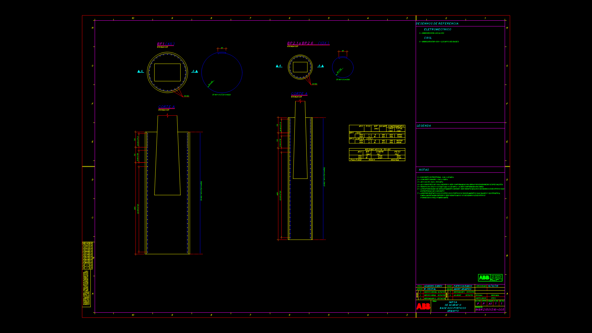
Building Elevation Plan with Steel Column and Foundation Detail

Architectural elevation drawing showing a building with multiple structural components and construction details. The plan features steel columns (300x300mm), concrete foundations, and UB305x165x40 universal beams. Key elements include:
Structural Components:
– Reinforced concrete columns with 12mm diameter rebar spaced at 15cm
– Steel plate connections (500x300x12mm and 250x250x12mm)
– Waterproofing layers at floor level (+0.2m)
– Foundation details with specified concrete cover
Technical Specifications:
– Floor elevation at +9.15m from base level
– Load-bearing walls with minimum 1.5% slope for drainage
– UNP 80mm channels used for framing elements
– L-profile steel members (50x50x2mm) at 45cm spacing
The drawing includes various section markers (D.01-D.08) corresponding to detail callouts and includes moisture barrier specifications with sand-cement rendering. Scale indicated as 1:50 with a grid reference system for coordination with other project documents.
| Language | Other |
| Drawing Type | Elevation |
| Category | Construction Details & Systems |
| Additional Screenshots | |
| File Type | dwg |
| Materials | Concrete, Steel |
| Measurement Units | Metric |
| Footprint Area | 150 - 249 m² (1614.6 - 2680.2 ft²) |
| Building Features | |
| Tags | concrete reinforcement, construction joints, foundation details, steel columns, structural elevation, universal beams, waterproofing |
Related Products


Same Contributor

Featured Products


