Industrial Centrifuge Machine Assembly Drawing with Power Pack
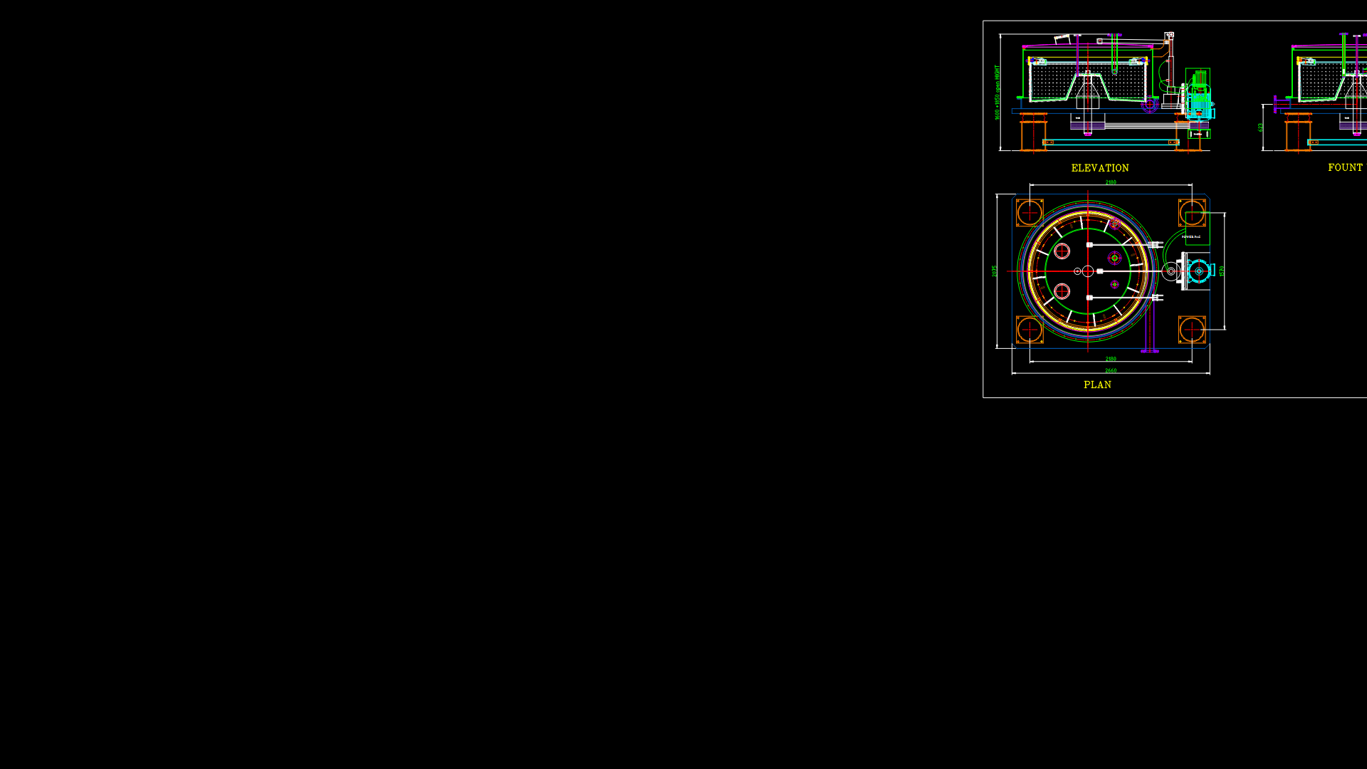
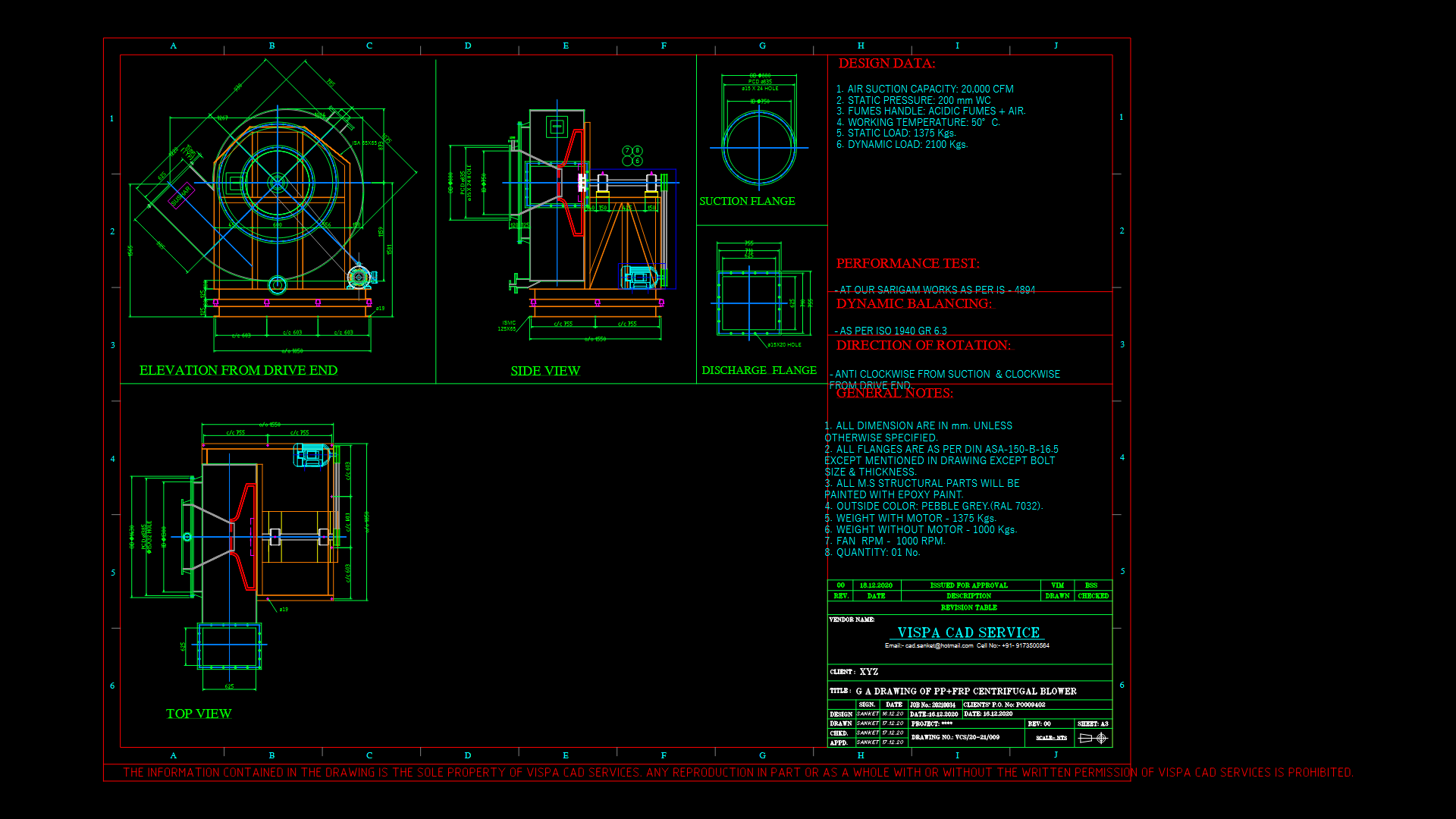
This comprehensive technical drawing presents a multi-view layout of an industrial centrifuge machine with integrated power pack. The drawing includes plan, elevation, and front views showing the critical operational components and mounting configuration. The centrifuge features a cylindrical separation chamber with internal rotating elements visible in the plan view, supported by a robust frame structure. Key specifications include a 15 Std NB connection point and overall height dimensions of 1600+1850mm when open. The design incorporates a back liner for containment and protection against material splatter during high-speed operation. The power pack is positioned adjacent to the main centrifuge body, connected via what appears to be hydraulic or electrical coupling systems. The circular design of the centrifuge facilitates optimal radial force distribution during operation; mounting points are clearly indicated at the four corners of the base frame. This centrifuge would typically be utilized in industrial separation processes where solid-liquid separation at high G-forces is required.
| Language | English |
| Drawing Type | Full Project |
| Category | Industrial |
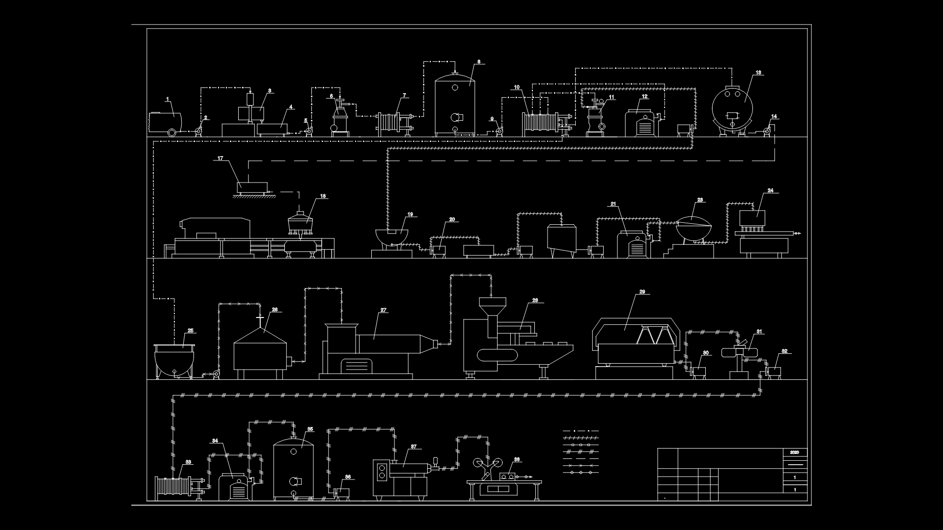
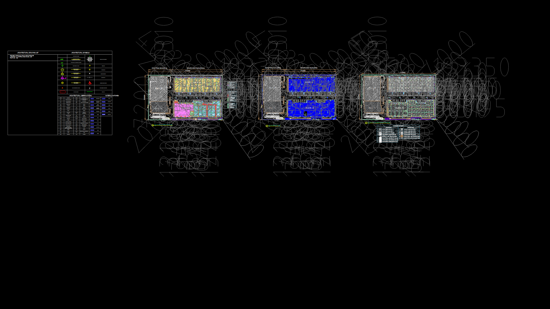
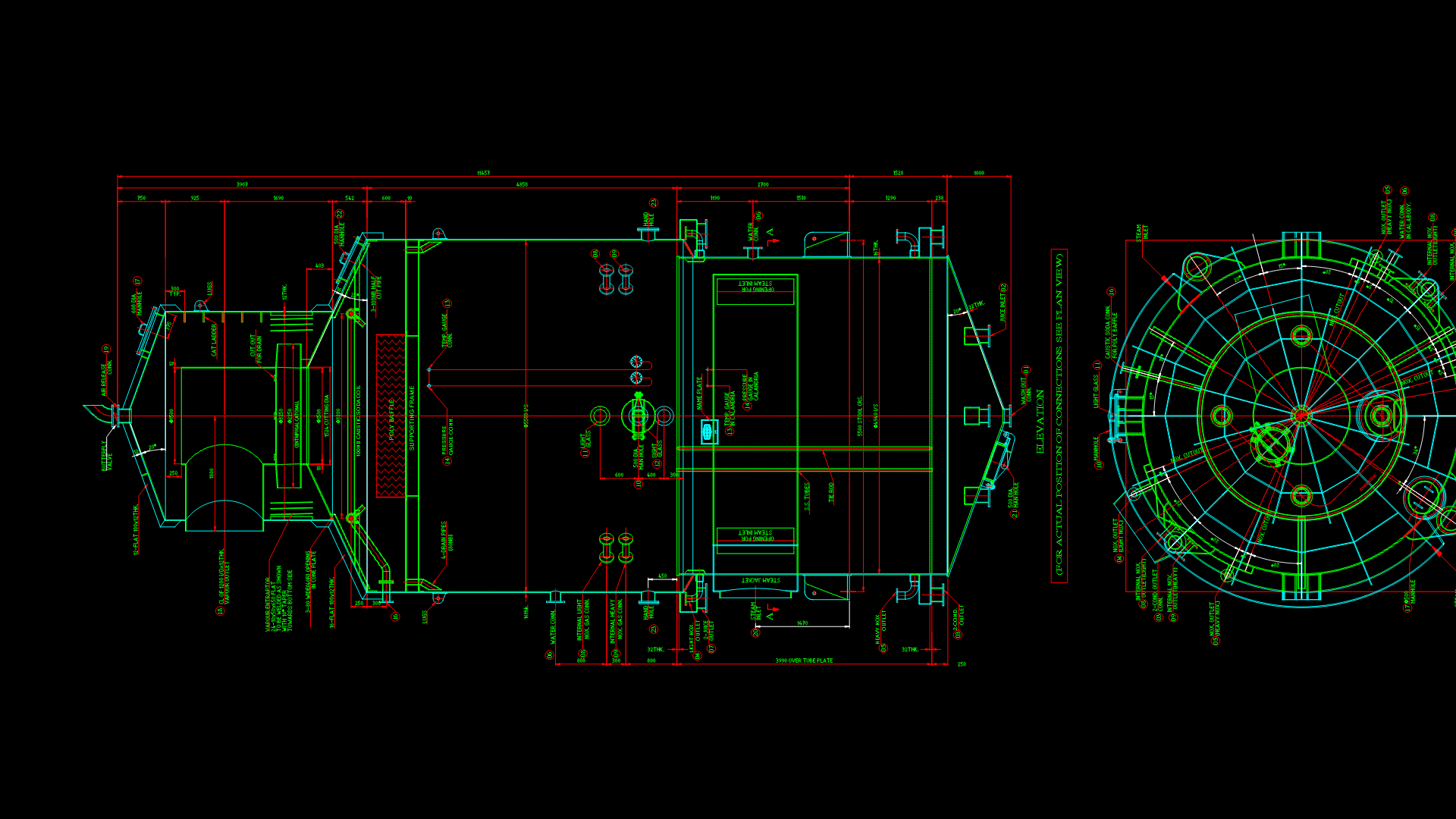
| Additional Screenshots |
 |
| File Type | dwg |
| Materials | Steel |
| Measurement Units | Metric |
| Footprint Area | 1 - 9 m² (10.8 - 96.9 ft²) |
| Building Features | |
| Tags | CENTRIFUGE, industrial separator, manufacturing equipment, mechanical assembly, power pack, process equipment, solid-liquid separation |
Related Products
Same Contributor

Featured Products


