Pump Pit Detail DWG Detail for AutoCAD
Pump pit detail
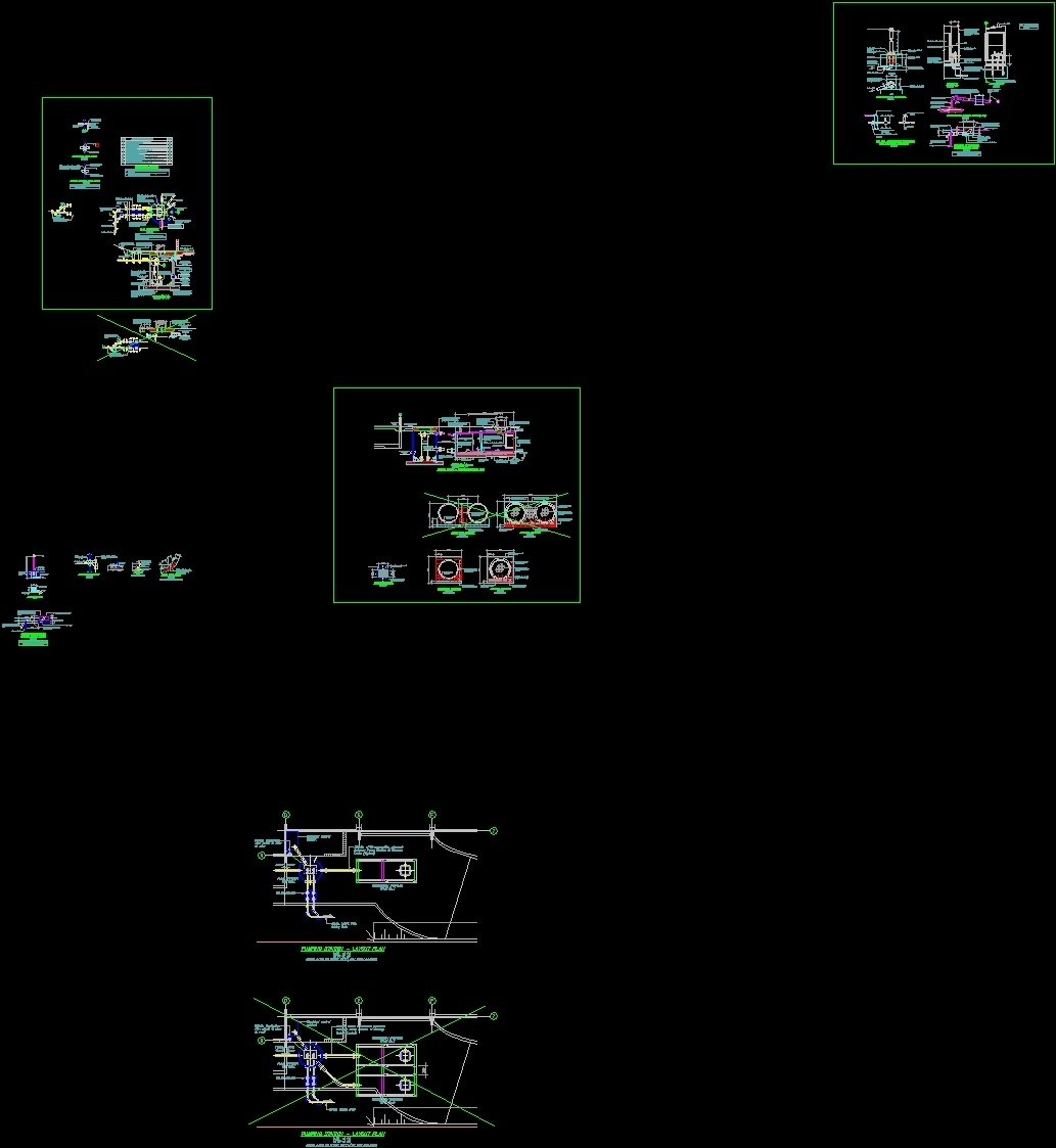
Drawing labels, details, and other text information extracted from the CAD file:
of shts, job no., revision, sheet no., sheet title, project, designed, file, client, drawn, checked, approved, no. revisions, ref, date, print date, date, appvd, jul, a.r.bird, jul, thick galv. m.s pipe long, i.d., approx, to suit, precast riser section, mesh, galvanised wire cage, stirrups at, extend into control cabinet plinth, fms fillets, bolts, dry pack mortar, pvc vent connection. provide min. fall, thick galv. m.s pipe long, electrical control cabinet plinth, fms base plate drilled for bolts on pitch circle dia, pvc duct to electrical control cabinet, wide conc encasing to pipe, slow radius bend, stirrups at, pump well wall, pvc bend. cut top half of pipe for easy access to pipe, electrical control cabinet plinth locate as shown on site plan provide cable access as noted below, to pump well, elevation of electrical, pumping station vent detail, control cabinet plinth, electrical contractor’s requirements., note: allow to provide slow radius bend, duct in plinth for mains supply cable to, outside, inside, butyl mastic sealing strip, top bottom with stirrups at crs in addition to reinforcing shown on section, cover edge detail, applies at corner of access cover, seal inside and outside of joint with quick set hume bond., riser joint detail, no. off equally spaced around perimeter of each wet well riser section, s.s threaded rod with washer nut and locknut at each end, s.s eyebolts countersunk into manhole riser and sealed with quick set hume bond., water hammer control device, valves for maintenance., from wall to allow access to both swing check, control. attach to valve pit walls. out, hdpe air inlet pipe for water hammer, pumping station vent detail, or tapping band., elongated gibault joint, elongated gibault joint., galv. pipe tapped into, swing check valve, flow, electrical control cabinet, see specification, funnel drain, beneath pressure relief, valve. also provide, drainage to cabinet floor., note: all steelwork to be hot, aligned., dia vertically, end cap with, class hdpe pipe, flow, line top of compartment, with salmac insulation, board or similar approved, including sides door, control cabinet., galv. pipe., lockable door as for, r.p. principle backflow, preventer or similar approved., concrete to support valves, drainage outlet to wet well, galv. pipes embedded in, shelf, by engineer, alarm light, dipped galvanised after, fabrication, plinth reinf. stirrups at, check with electrical contractor, s.s solenoid valve on timer., to pump well, under baseplate, electrical contractor’s requirements., duct in plinth for mains supply cable to, slow radius bend, control cabinet, finished gd. level., note: allow to provide slow radius bend, wide conc encasing to pipe, pvc duct to electrical, n.t.s., ground level, elevation, thick galv. m.s. pipe, into control cabinet plinth, to extend, stirrups at, above finished, below, pipe, pump well wall, electrical control cabinet plinth, locate as shown on site plan, provide cable access as noted, upvc bend. cut top half, of pipe for easy access to, plan, tee, electrical control cabinet, plinth and water cubicle, fms gussets, galvanised wire cage, bolts, f.j., thick drypack mortar, pvc vent, connecti
Raw text data extracted from CAD file:
| Language | English |
| Drawing Type | Detail |
| Category | Industrial |
| Additional Screenshots |
 |
| File Type | dwg |
| Materials | Concrete, Steel, Other |
| Measurement Units | |
| Footprint Area | |
| Building Features | |
| Tags | autocad, bomba, bomba de água, DETAIL, DWG, pipe, pit, pompe, pompe à eau, pump, pumpe, rohr, tubulação, tuyaux, wasserpumpe, water pump |
Related Products

Same Contributor


Featured Products


