Residential Shear Wall Holddown Connection Detail Drawing Set
Comprehensive Wood-Frame Shear Wall Detail Package
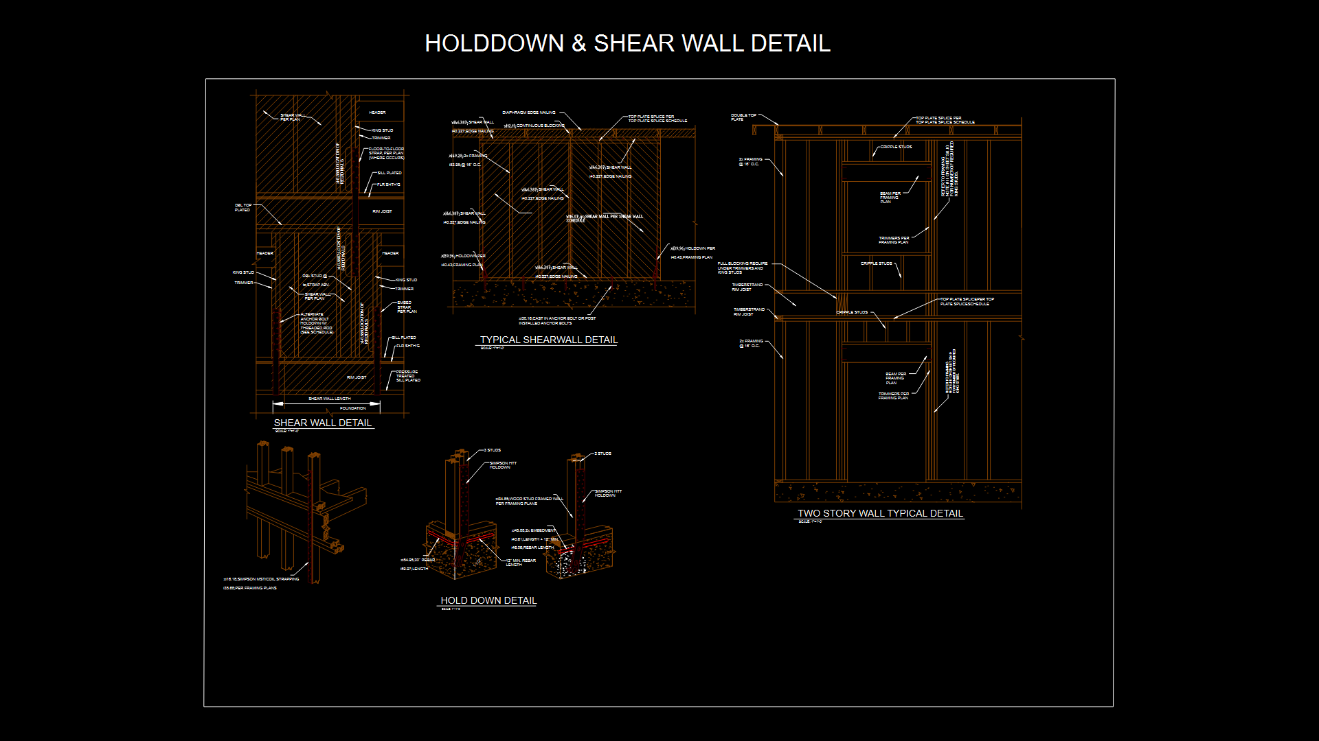
This structural engineering detail drawing provides essential connection specifications for wood-frame shear wall assemblies in residential construction. The drawing consists of four interconnected details:
1. Typical Shear Wall Detail: Illustrates the complete assembly with double top plates, 2x framing at 16″ O.C., edge nailing requirements, and continuous blocking. Shows proper connection between sheathing, framing members, and foundation elements with specified load capacities ranging from 2000 to 5100 lbs.
2. Holddown Detail: Depicts Simpson HTT holddown installation with specified anchor bolt requirements, rebar embedment (minimum 12″ length), and proper stud configuration. The detail shows cast-in or post-installed anchor options with specific fastening patterns.
3. Two-Story Wall Detail: Demonstrates vertical load path continuity through floor systems using MST/coil strapping (per framing plans). Features include:
– Double top plate with splice connections
– TimbStrand rim joist configuration
– Floor-to-floor strap placement
– Trimmer and king stud requirements with full blocking support
4. Shear Wall Detail: Illustrates foundation-to-wall connections including pressure-treated sill plate, rim joist, and proper nailing patterns. Includes alternate anchor bolt holddown with threaded rod options.
Each detail is drawn at 1″=1′-0″ scale in imperial units, providing critical information for proper lateral force-resisting system implementation in accordance with structural engineering requirements.
| Language | English |
| Drawing Type | Detail |
| Category | Construction Details & Systems |
| Additional Screenshots | |
| File Type | dwg |
| Materials | Wood |
| Measurement Units | Imperial |
| Footprint Area | N/A |
| Building Features | |
| Tags | Holddown Connection, Lateral Force-Resisting System, Shear Wall, Simpson HTT, Simpson Strapping, structural engineering, Wood Framing |
Related Products


Same Contributor

Featured Products


