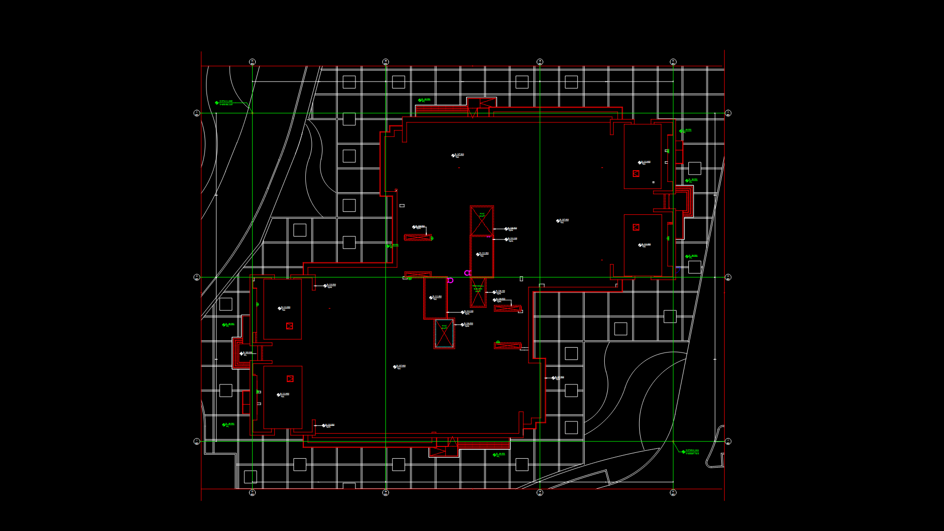
Solar Power Plant Foundation Plan for 17.6 MVA ICR with Isolated Footings

This foundation layout drawing for a 17.6 MVA Inverter Control Room (ICR) shows isolated reinforced concrete footings at a depth of -1.5m from natural ground level. This drawing details three types of footings (F1, F2, F3) with their respective dimensions and reinforcement schedules. F1 footings measure 4000×2700×350mm with Y12@100mm c/c bottom reinforcement. F2 footings are 5000×2600×350mm, while F3 footings are 3000×3000×300mm. The drawing includes typical sections showing pedestal details (P1 size 450×450mm) with 4-Y20 main reinforcement and Y8@100mm c/c stirrups. Ground improvement specifications require 800-1200mm soil replacement with granular fill compacted to 95% MDD. All concrete is specified as M30 grade with CRS/FBEC rebar (Fe500 grade). The foundation supports multiple equipment pieces including 4.4MW inverters, transformers, auxiliary panels, and NIFPS systems for a 300 MWac solar ground-mounted project in Khavda, Gujarat.
| Language | English |
| Drawing Type | Plan |
| Category | Construction Details & Systems |
| Additional Screenshots |
 |
| File Type | dwg |
| Materials | Concrete, Steel |
| Measurement Units | Metric |
| Footprint Area | 1000 - 2499 m² (10763.9 - 26899.0 ft²) |
| Building Features | |
| Tags | ground improvement, inverter station, isolated footing, M30 concrete, reinforcement details, solar foundation, transformer foundation |
Related Products


Same Contributor
Featured Products


